
Offset interconnect for a solid oxide fuel cell and method of making same

a fuel cell and interconnection technology, applied in the field of fuel cell components, can solve the problems of insufficient applicability, limited cell area, and difficult to reliably produce seals,

Inactive Publication Date: 2005-10-13
BLOOM ENERGY CORP
View PDF13 Cites 109 Cited by
  • Summary
  • Abstract
  • Description
  • Claims
  • Application Information

AI Technical Summary

Benefits of technology

The present invention provides an interconnect for a solid oxide fuel cell that includes a non-ionically and non-electrically conductive ceramic gas separator plate with first and second vias, and a plurality of electrically conductive fillers connected in the vias. The first and second vias are offset from each other. The interconnect has improved electrical conductivity and can connect to the fuel cell's interconnecting body. The invention also provides a method for making the interconnect. The technical effects of the invention include improved electrical conductivity and reliable connection to the fuel cell's interconnecting body.

Problems solved by technology

These approaches have not been completely satisfactory.
The tailored metal alloy approach meets all the desired characteristics except that it is limited to a matching CTE that is only within about 10% of the solid oxide electrolyte.
As a result of this CTE limitation, the area of the cell is limited in order to avoid stressing the electrolyte beyond its capability.
Additionally, the seals are more difficult to be reliably produced and the electrolyte thickness must be proportionally thicker to have the strength to counteract the minor CTE mismatch.
However, these electrically conductive ceramics are expensive and difficult to fabricate, their chemical compatibility with the electrodes is lower than desired and the CTE mismatch of these ceramics with the electrolyte remains higher than desired.
However, this configuration is susceptible to undesirable cross interconnect reactant permeability (i.e., leakage of the fuel and oxidant through the separator plate).

Method used


Image

  • Offset interconnect for a solid oxide fuel cell and method of making same
  • Offset interconnect for a solid oxide fuel cell and method of making same
  • Offset interconnect for a solid oxide fuel cell and method of making same

Examples


Embodiment Construction

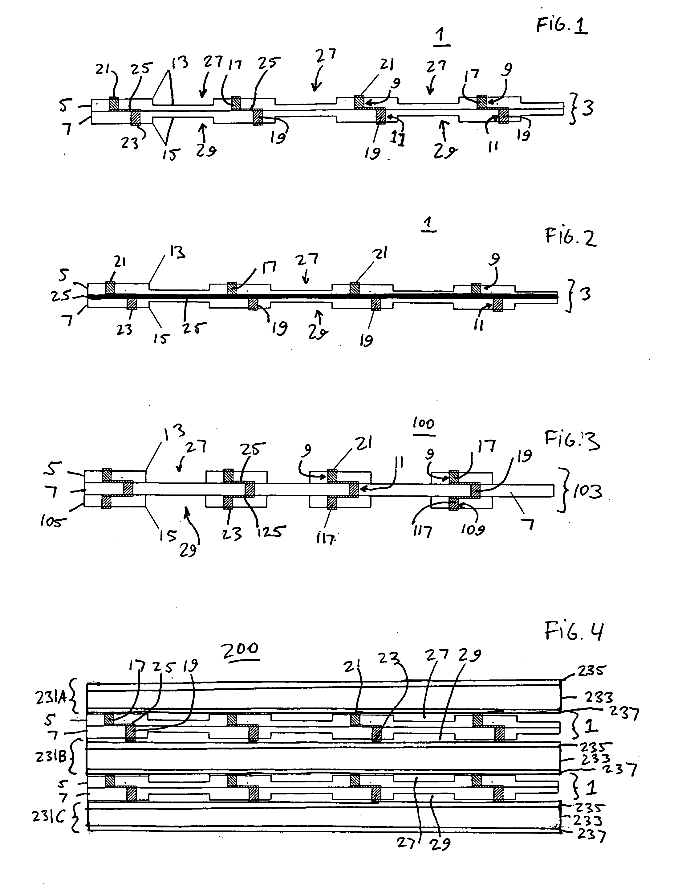
[0013] The present inventor has realized that an interconnect comprising a ceramic gas separator plate made from a CTE matched, non-electrically conductive ceramic material but without vias extending through the gas separator plate, reduces or eliminates the undesirable cross interconnect reactant permeability (i.e., leakage of the fuel and oxidant through the separator plate) and still meets all of the other desired characteristics of a functional interconnect.

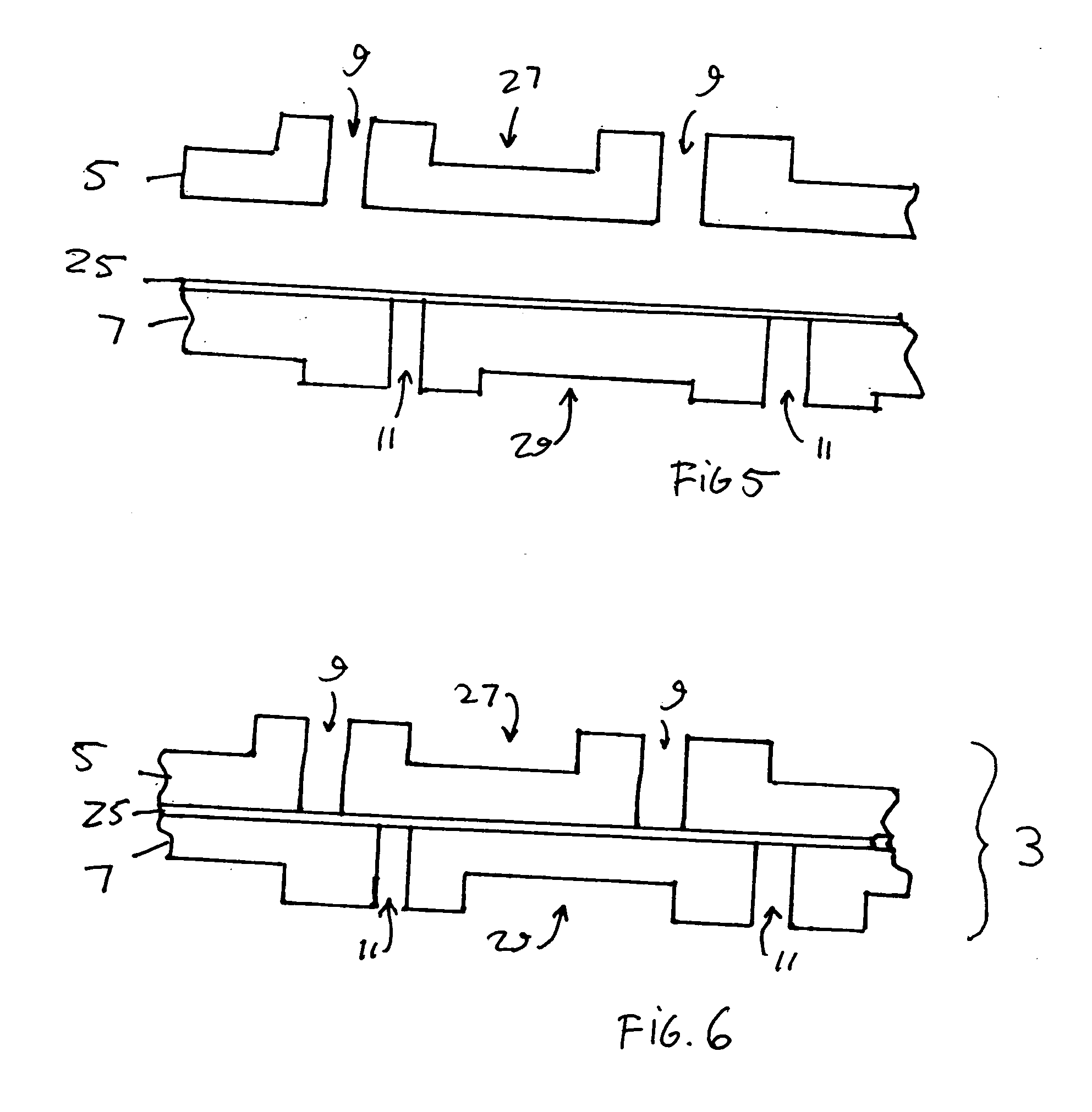
[0014] The interconnect contains a non-ionically and non-electrically conductive ceramic gas separator plate that contains at least two ceramic layers. A plurality of first vias extend through the first separator plate ceramic layer but not through the second separator plate ceramic layer. A plurality of second vias extend through the second separator plate ceramic layer but not through the first separator plate ceramic layer. The second vias are offset from the first vias. The term “offset” means that when the vias are view...


PUM

PropertyMeasurementUnit
thicknessaaaaaaaaaa
sizeaaaaaaaaaa
thicknessaaaaaaaaaa

Abstract

An interconnect for a solid oxide fuel cell includes a non-ionically and non-electrically conductive ceramic gas separator plate comprising at least two ceramic layers, a plurality of first vias extending through the first separator plate ceramic layer but not through the second separator plate ceramic layer and a plurality of second vias extending through the second separator plate ceramic layer but not through the first separator plate ceramic layer. The second vias are offset from the first vias. The interconnect also includes a plurality of electrically conductive first fillers located in the plurality of first vias and a plurality of electrically conductive second fillers located in the plurality of second vias. Each of the plurality of first fillers is electrically connected to at least one second filler.

Description

BACKGROUND OF THE INVENTION [0001] The present invention is generally directed to fuel cell components and more specifically to interconnects for solid oxide fuel cells. [0002] Fuel cells are electrochemical devices which can convert energy stored in fuels to electrical energy with high efficiencies. One type of high temperature fuel cell is a solid oxide fuel cells which contains a ceramic (i.e., a solid oxide) electrolyte, such as a yttria stabilized zirconia (YSZ) electrolyte. One component a planar solid oxide fuel cell stack or system is the so called gas separator plate that separates the individual cells in the stack. The gas separator plate separates fuel, such as hydrogen or a hydrocarbon fuel, flowing to the anode of one cell in the stack from oxidant, such as air, flowing to a cathode of an adjacent cell in the stack. Frequently, the gas separator plate is also used as an interconnect which electrically connects the anode electrode of one cell to a cathode electrode of th...

Claims


Application Information

Patent Timeline
Patent Type & Authority Applications(United States)
IPC IPC(8): B23P19/00H01M2/00H01M2/14H01M8/02H01M8/10H01M8/12H01M8/24
CPCH01M8/0217H01M8/0228H01M8/0232H01M8/0236H01M8/0256H01M8/1253Y10T29/49112H01M2008/1293Y02E60/50Y02E60/525Y10T29/53135Y10T29/532H01M8/2425H01M8/0258H01M8/2404H01M8/2432Y02P70/50
Inventor NGUYEN, DIEN
Owner BLOOM ENERGY CORP
Learn More