Power conversion device

a power conversion device and power conversion technology, applied in the direction of dc-ac conversion without reversal, semiconductor lasers, etc., can solve the problems of power conversion device out of order, power conversion device functions are restricted, diode element temperature exceeds, etc., to achieve high power generation efficiency and small amount of hea

Inactive Publication Date: 2005-10-13
MITSUBISHI ELECTRIC CORP
View PDF5 Cites 16 Cited by
  • Summary
  • Abstract
  • Description
  • Claims
  • Application Information

AI Technical Summary

Benefits of technology

[0010] The present invention was made to solve the above-mentioned problems and has an object of providing a power conversion device of which functions are less likely to be restricted due to overheat of any diode element by causing the diode element at the time of power generation operation to generate a smaller amount of heat, and which possesses a high power generation efficiency.

Problems solved by technology

Therefore, supposing that no restriction of current flow is made, a temperature of the diode element exceeds an allowable temperature range, and eventually there will be some cases where a power conversion device is out of order.
However, since the overheat of a diode element 9 is prevented by suppressing or stopping the power generation operation, a problem exists in that functions of a power conversion device are restricted.
Thus, a problem exits in that the operation of generating a large electric power cannot be carried out continuously.
In addition, there is a large loss in the power conversion device at the time of power generation operation, resulting in a further problem of low power generation efficiency.

Method used


Image

  • Power conversion device
  • Power conversion device
  • Power conversion device

Examples


embodiment 1

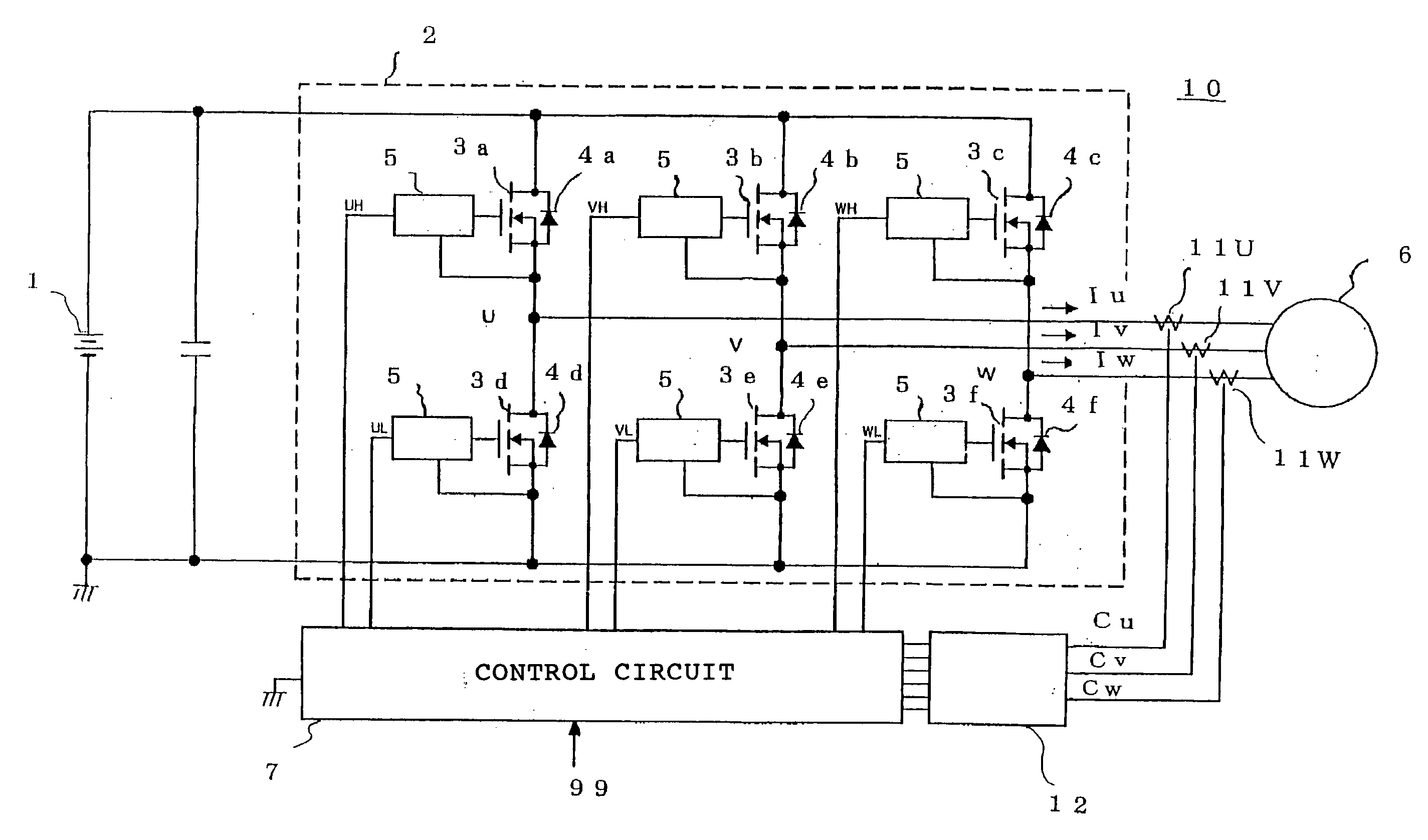
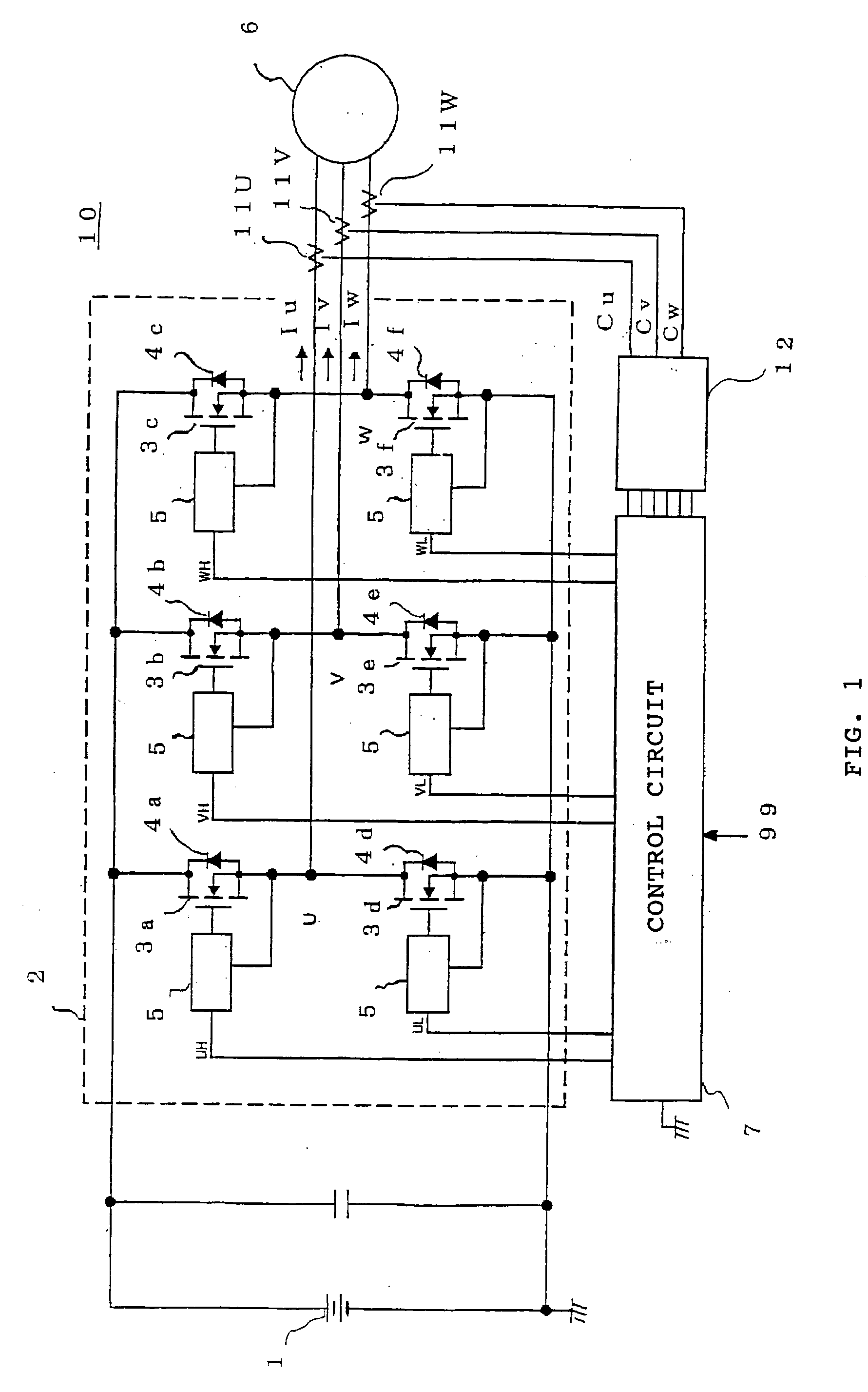
[0024] A schematic diagram of the entire arrangement of a power conversion device according to a first preferred embodiment of the present invention is shown in FIG. 1. Positive (+) and negative (−) terminals of a DC power supply 1 are connected to a power conversion section 2 of a power conversion device 10. The power conversion section 2 includes three switching elements 3a, 3b, 3c that are connected to the positive terminal of the DC power supply 1 (for example, a MOS-type transistor having an ON resistance of several mΩ) and three switching elements 3d, 3e, 3f that are likewise connected to the negative terminal of the DC power supply. To these six switching elements 3a, 3b, 3c, 3d, 3e, 3f, diode elements (hereinafter, merely referred to as diodes) 4a, 4b, 4c, 4d, 4e are connected in parallel respectively. For convenience of the description, a part formed of the switching elements 3a, 3b, 3c, 3d, 3e, 3f is hereinafter referred to as a first power conversion section. A part forme...

embodiment 2

[0043] In the foregoing first embodiment, three phases of current sensors 11 are provided as shown in FIG. 1. As shown in FIG. 4, however, on the supposition of mounting only any two phases of current sensors out of U, V and W phases, a current value of the remaining one phase (instantaneous value) can be calculated by simple operation. FIG. 4 shows the entire arrangement of a power conversion device in this sense. Hereinafter, in the drawings, same reference numerals as those in FIGS. 1, 2 and 3 indicate the same or like parts, and detailed descriptions thereof are omitted.

[0044]FIG. 4 shows the case where current sensors 11 are mounted on two lines of U phase and V phase to detect currents of these two phases, and a current of W phase is obtained by the operation of currents of these two phases (it is referred to as current operation circuit).

[0045]FIG. 5 shows the arrangement of a synchronous rectifier gate signal generation circuit 22 of FIG. 4. The synchronous rectifier gate ...

embodiment 3

[0047] Various types of current sensors 11 are employed for use in vehicles. In some cases where a zero-point voltage output from a current sensor is poor in the aspect of precision (drift of a DC component occurs) as is the case of current sensors employing, for example, a Hall element, ideal output signals from a current sensor can be obtained so as to obtain accurately a direction of phase currents by AC coupling of output signals from the current sensor to interrupt a DC drift component. FIG. 6 shows a synchronous rectifier gate signal generation circuit 23 arranged to perform such an advantage.

[0048]FIG. 6 shows an example in which the arrangement according to this third embodiment is applied to the one of FIG. 5 according to the foregoing second embodiment in order to facilitate further understanding. In the drawing, an adding inverting circuit 22a, a comparator 22c, an AND gate 22d and the like are the same as those in FIG. 5, so that further description thereof is omitted. ...


PUM


Abstract

A large amount of heat generation is incidental to conventional power conversion devices due to large ion voltage of a diode element rectifying AC power to DC power. Moreover, in the heat generation, power generation operation has to be stopped to prevent burnout of the diode element, resulting in restriction on power conversion functions. In the power generation mode that diode elements 4 rectifies an AC power generated by a generator-motor 6, a diode element being in conduction state is detected out of the diode elements 4 in accordance with an output signal from a current sensor mounted on an AC power line of the generator-motor 6, and a switching element 3 that is connected in parallel with the diode element 4 is turned ON. Most of current of the diode element 4 flow through the switching element 3, resulting in reduction of heat generation of the diode element 4.

Description

BACKGROUND OF THE INVENTION [0001] 1. Field of the Invention [0002] The present invention relates to an improvement of a power conversion device to be inserted between a DC power supply and an AC generator-motor. [0003] 2. Description of the Related Art [0004] In a hybrid electric vehicle, a power conversion device is used. This power conversion device serves to convert a DC electric power of a DC power supply such as battery into an AC power having an arbitrary frequency to drive an AC motor, and to rectify an AC power having been generated to charge the mentioned DC power supply when the AC motor operates as a generator (for example, at the time of regenerative braking). [0005] A power conversion device, for example, as disclosed in FIG. 2 of the Japanese Patent Publication (unexamined) No. 191691 / 1998 includes an inverter module 10 that is arranged of a plurality of switching elements 8 and a plurality of diode elements 9, and AC / DC conversion operation is performed with this arr...

Claims


Application Information

Patent Timeline
Patent Type & Authority Applications(United States)
IPC IPC(8): E04F13/08B60L11/00B60L11/18H01S5/00H02M7/12H02M7/219H02M7/48H02M7/757H02P23/06
CPCH02P23/06H02M7/219
Inventor ASAI, TAKAMASA
Owner MITSUBISHI ELECTRIC CORP
Why Eureka
Try Eureka