
Motor vehicle

a motor vehicle and vehicle body technology, applied in the direction of electric devices, battery/fuel cell control arrangements, battery/cell propulsion, etc., can solve the problems of occupying some space in the passenger compartment and undetectedly limiting the space in the trunk room, and achieve the effect of favorable loading balance over the vehicl

Inactive Publication Date: 2005-10-13
TOYOTA JIDOSHA KK
View PDF10 Cites 39 Cited by
  • Summary
  • Abstract
  • Description
  • Claims
  • Application Information

AI Technical Summary

Benefits of technology

[0007] The motor vehicle of the invention thus aims to ensure sufficient spaces in a passenger compartment and in a trunk room on the rear side of the vehicle. The motor vehicle of the invention also aims to have a favorable loading balance over the vehicle.
[0010] In the motor vehicle of the invention, the fuel tank is located in the vicinity of the front axle and stores the gaseous fuel to be supplied to the power output apparatus, which receives the supply of gaseous fuel and outputs driving power. This layout does not occupy the spaces of a passenger compartment and a trunk room on the rear side of the vehicle and thus ensures the sufficient spaces in the passenger compartment and in the trunk room on the rear side of the vehicle. The arrangement of the fuel tank in the vicinity of the axle enables the load of the fuel tank to be directly applied to the axle and thereby desirably reduces the required weight of a support member for supporting the fuel tank. The ‘fuel tank’ may store hydrogen or a hydrogen-containing gas as the gaseous fuel.
[0011] In one preferable embodiment of the invention, the motor vehicle has a shock absorbing member that is mounted on a foremost part of the vehicle to absorb impact of a front collision, and the fuel tank is located to partly overlap a mounting height of the shock absorbing member. This arrangement desirably reduces a potential shock to the fuel tank in the event of a vehicle collision.
[0012] In the motor vehicle of the invention, it is preferable that the fuel tank is arranged to have its longitudinal axis along a width of the vehicle. This arrangement ensures the good loading balance over the width of the vehicle.
[0014] In the fuel cell vehicle according to the structure of the invention, the fuel cells may be located in the passenger compartment. This arrangement desirably reduces potential effects due to the contact of the fuel cells with the outside air. The fuel cells may be located under a seat or more specifically may be located under a front seat or under a rear seat to be stacked along the width of the vehicle. This arrangement ensures the effective use of a potentially dead space in the passenger compartment and gives the good loading balance over the width of the vehicle.

Problems solved by technology

The increased volume of the fuel tanks located under the floor of the passenger compartment, however, naturally takes some space of the passenger compartment.
The demand of increasing the volume of the fuel tanks is thus rather contradictory to the demand of ensuring the sufficient space of the passenger compartment.
This layout, however, undesirably limits the space of the trunk room.

Method used


Image

  • Motor vehicle
  • Motor vehicle
  • Motor vehicle

Examples


Embodiment Construction

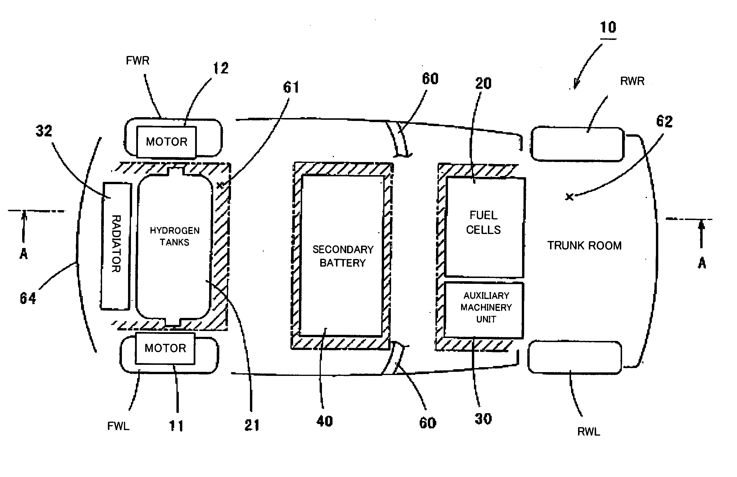
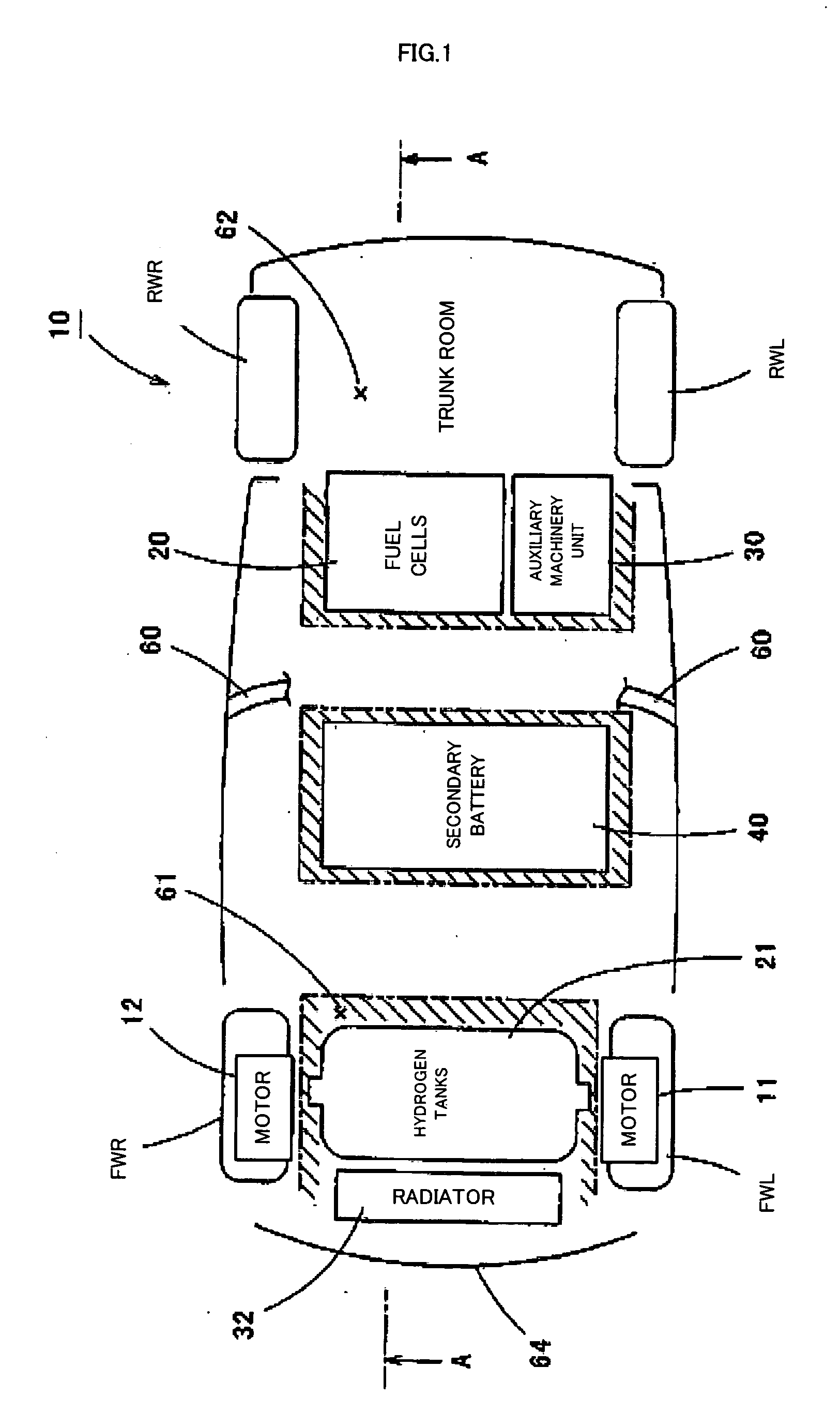
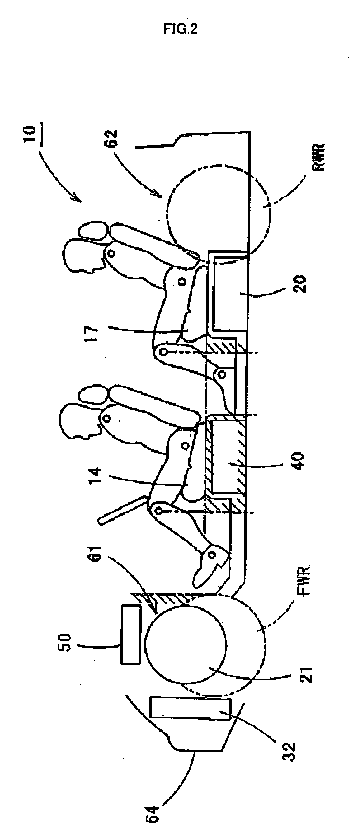
[0019] One mode of carrying out the invention is discussed below as a preferred embodiment. FIG. 1 is a plan view schematically illustrating the configuration of a fuel cell vehicle 10 in one embodiment of the invention. FIG. 2 is a sectional view showing the fuel cell vehicle 10 of the embodiment, taken on a line A-A of FIG. 1. FIG. 3 is a block diagram showing functional blocks of the fuel cell vehicle 10 of the embodiment.

[0020] As illustrated, the fuel cell vehicle 10 of the embodiment includes a left wheel motor 11 that is built in a left front wheel FWL, a right wheel motor 12 that is built in a right front wheel FWR, a secondary battery 40 that is located under a front seat 14, fuel cells 20 and an auxiliary machinery unit 30 that are located under a rear seat 17, hydrogen tanks 21 that are located in a front section of the vehicle and store hydrogen therein to be supplied to the fuel cells 20, a radiator 32 that radiates heat of cooling water running through the fuel cells ...


PUM


Abstract

Hydrogen tanks 21 are located in the vicinity of a front axle of a left front wheel FWL and a right front wheel FWR in a front space 61 of a motor vehicle and are arranged to have their longitudinal axis along a width of the vehicle. The hydrogen tanks 21 are positioned at a height substantially the same as a mounting height of a front bumper 64. This layout desirably ensures sufficient spaces in a trunk room 62 on the rear side of the vehicle and in a passenger compartment of the vehicle. This layout also enables the load of the hydrogen tanks 21 to be directly applied to the left and right front wheels FWL and FWR, while ensuring the good weight balance over the width of the vehicle. The positioning of the hydrogen tanks 21 at substantially the same height as the mounting height of the front bumper 64 effectively reduces a potential shock to the hydrogen tanks 21 in the event of a vehicle collision.

Description

CROSS-REFERENCE TO RELATED APPLICATION [0001] This is a continuation of Application PCT / JP03 / 09095, filed Jul. 17, 2003, now abandoned.BACKGROUND OF THE INVENTION [0002] 1. Field of the Invention [0003] The present invention relates to a motor vehicle. [0004] 2. Description of the Prior Art [0005] In one proposed layout of a motor vehicle, fuel cells are located in the vicinity of either a front axle or a rear axle, while fuel tanks for supplying a fuel to the fuel cells are located under the floor of a passenger compartment to be positioned near to the fuel cells (see, for example, Japanese Patent Laid-Open Gazette No. 2001-253248). This proposed layout of the motor vehicle ensures the supply of hydrogen to the fuel cells without occupying the space of the passenger compartment and an available storage capacity of the vehicle. [0006] The increased volume of the fuel tanks located under the floor of the passenger compartment, however, naturally takes some space of the passenger comp...

Claims


Application Information

Patent Timeline
IPC IPC(8): B60K15/03B60K7/00B60L11/18B60K1/02B60K15/063B60K1/04
CPCB60K1/02B60L50/71B60K7/0007B60K15/063B60K2001/005B60K2015/0637B60L3/0007B60L3/0069B60L3/0092B60L2220/44Y02T10/705Y02T90/34F17C11/005Y02E60/321B60L50/51B60L50/66B60L58/40B60L58/33B60L58/34B60K1/04Y02E60/32Y02T10/70Y02T90/40B60L50/72B60K15/07B60K2015/03315B60K2001/0433B60K2001/0422
Inventor MIZUNO, MINOBU
Owner TOYOTA JIDOSHA KK
Learn More