Apparatus and method for forming thin film using upstream and downstream exhaust mechanisms

a technology of exhaust mechanism and thin film, applied in the direction of chemical vapor deposition coating, semiconductor/solid-state device details, coating, etc., to achieve the effect of improving throughput, short time period, and extremely uniform supply of source gases

Active Publication Date: 2005-09-22
ASM JAPAN
View PDF4 Cites 507 Cited by
  • Summary
  • Abstract
  • Description
  • Claims
  • Application Information

AI Technical Summary

Benefits of technology

[0051] In accordance with one embodiment of the thin-film formation apparatus according to the present invention, it becomes possible to supply source gases extremely uniformly by using a showerhead and to eliminate reaction gases remaining inside the showerhead in a short period of time, which were conventionally difficult. For example, by using a high-speed variable-conductance valve powered by a servomotor, it becomes possible to m

Problems solved by technology

In order to achieve uniform concentration distribution, controlling conductance in a flow path from the showerhead to the subst

Method used


Image

  • Apparatus and method for forming thin film using upstream and downstream exhaust mechanisms
  • Apparatus and method for forming thin film using upstream and downstream exhaust mechanisms
  • Apparatus and method for forming thin film using upstream and downstream exhaust mechanisms

Examples


embodiment 2

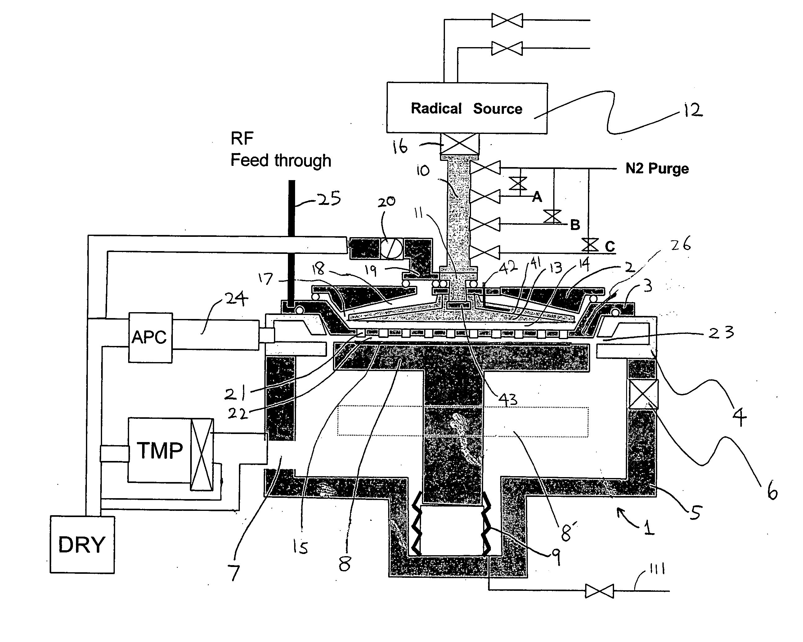
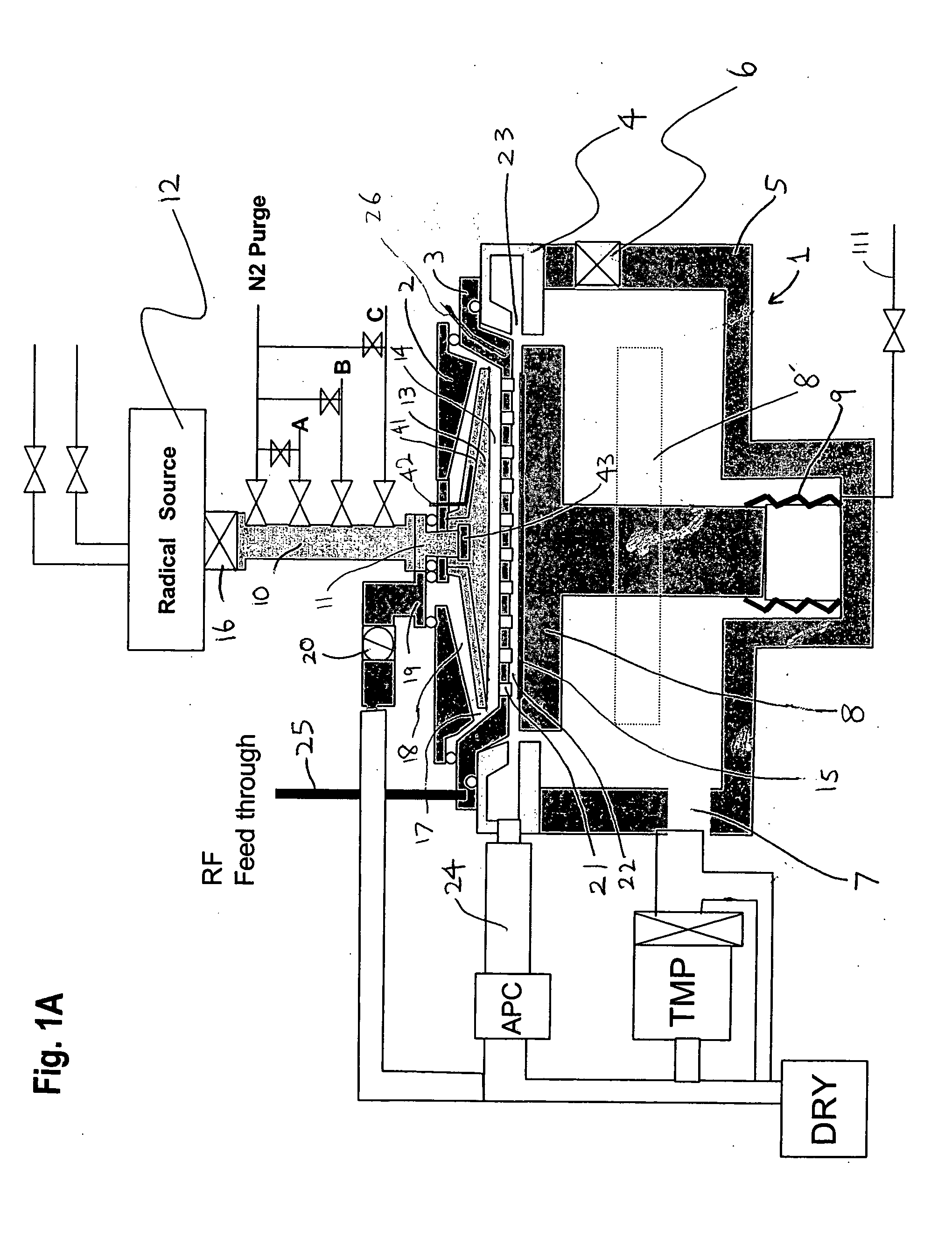
[0249] In this embodiment, a process of forming tantalum nitride films using tertiaryamylimidotris(dimethylamido)tantalum: TaN(C4H9)(NC2H6)3, an organic metal material of Ta, and NH3. After a silicon substrate is transferred from a vacuum transfer chamber (not shown in the figure) to the reaction chamber 1, remaining moisture, oxygen, etc. are evacuated satisfactorily using a turbo pump 7 (See FIG. 1A). The substrate is moved to a given position by a vertical movement mechanism of the substrate-heating stand 8. At this time, a gap between the dispersion plate 3 and a substrate surface is set at a value within the range of 2-8 mm. In this embodiment, the process was implemented by setting the gap at 5 mm.

[0250]FIG. 5 and FIG. 6 show a process sequence: A silicon substrate is transferred from a vacuum transfer chamber (not shown) to the reaction chamber 1. The reaction chamber is exhausted by the turbo pump to 10−6 Torr or below. After an amount of remaining gases including moisture ...


PUM

PropertyMeasurementUnit
Temperatureaaaaaaaaaa

Abstract

A thin-film formation apparatus possesses a reaction chamber to be evacuated, a placing portion on which a substrate is placed inside the reaction chamber, a gas-dispersion guide installed over the placing portion for supplying a gas onto a substrate surface, a gas-supply port for introducing the gas into the gas-dispersion guide, a gas-dispersion plate disposed on the side of the substrate of the gas-dispersion guide and having multiple gas-discharge pores, a first exhaust port for exhausting, downstream of the gas-dispersion plate, the gas supplied onto the substrate surface from the gas-dispersion plate, and a second exhaust port for exhausting, upstream of the gas-dispersion plate, a gas inside the gas-dispersion guide via a space between the gas-dispersion guide and the gas-dispersion plate.

Description

[0001] This application claims the benefit of U.S. Provisional Application No. 60 / 510,059, filed on Oct. 9, 2003.BACKGROUND OF THE INVENTION [0002] 1. Field of the Invention [0003] The present invention relates to a single-wafer-processing type thin-film formation apparatus and method, which form a thin film on a workpiece, which is a semiconductor wafer, piece by piece. [0004] 2. Description of the Related Art [0005] As thin-film formation apparatuses for thin film growth by atomic layer deposition, various types of formation apparatuses have been proposed. As typical examples, there are cases, in which gas is supplied from a gas-dispersion apparatus (i.e., a showerhead) disposed facing a substrate; and cases, in which gas is supplied by forming a laminar flow flowing in a direction from one edge of the substrate to the other edge without using the showerhead. In the case of a showerhead method, source gases can be supplied at uniform gas concentration onto the substrate surface, w...

Claims


Application Information

Patent Timeline
IPC IPC(8): C23C16/34C23C16/455C23C16/44H01J37/32H01L21/205H01L21/306
CPCC23C16/34C23C16/4412C23C16/45525H01J37/32834C23C16/45565H01J37/3244H01J37/32449C23C16/45544H01L21/205
Inventor SHINRIKI, HIROSHIKAWANO, BAIEISHIMIZU, AKIRA
Owner ASM JAPAN
Why Eureka
Try Eureka