
Bulk acoustic wave filter and method for eliminating unwanted side passbands

a filter and acoustic wave technology, applied in the field of bulk acoustic wave filters, can solve the problems of overmode-detuning components providing a mismatch of the thickness of the bottom electrodes beneath the piezo median plane, and achieve the effect of cost-effectiveness

Active Publication Date: 2005-09-15
AVAGO TECH INT SALES PTE LTD
View PDF9 Cites 16 Cited by
  • Summary
  • Abstract
  • Description
  • Claims
  • Application Information

AI Technical Summary

Benefits of technology

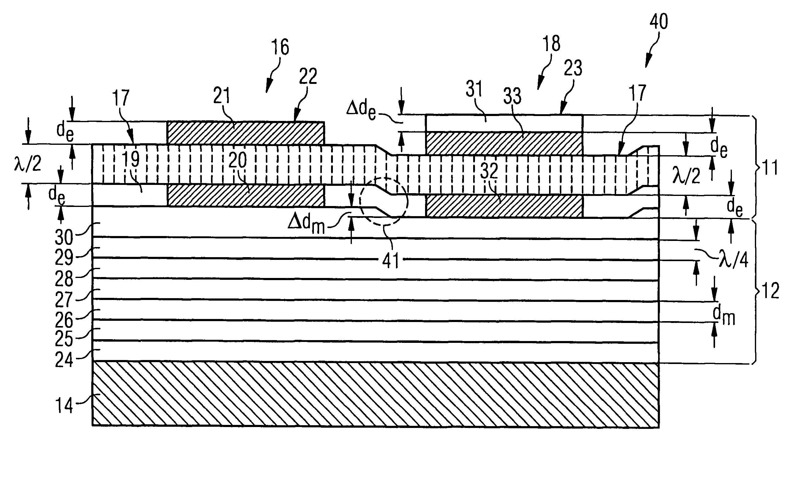
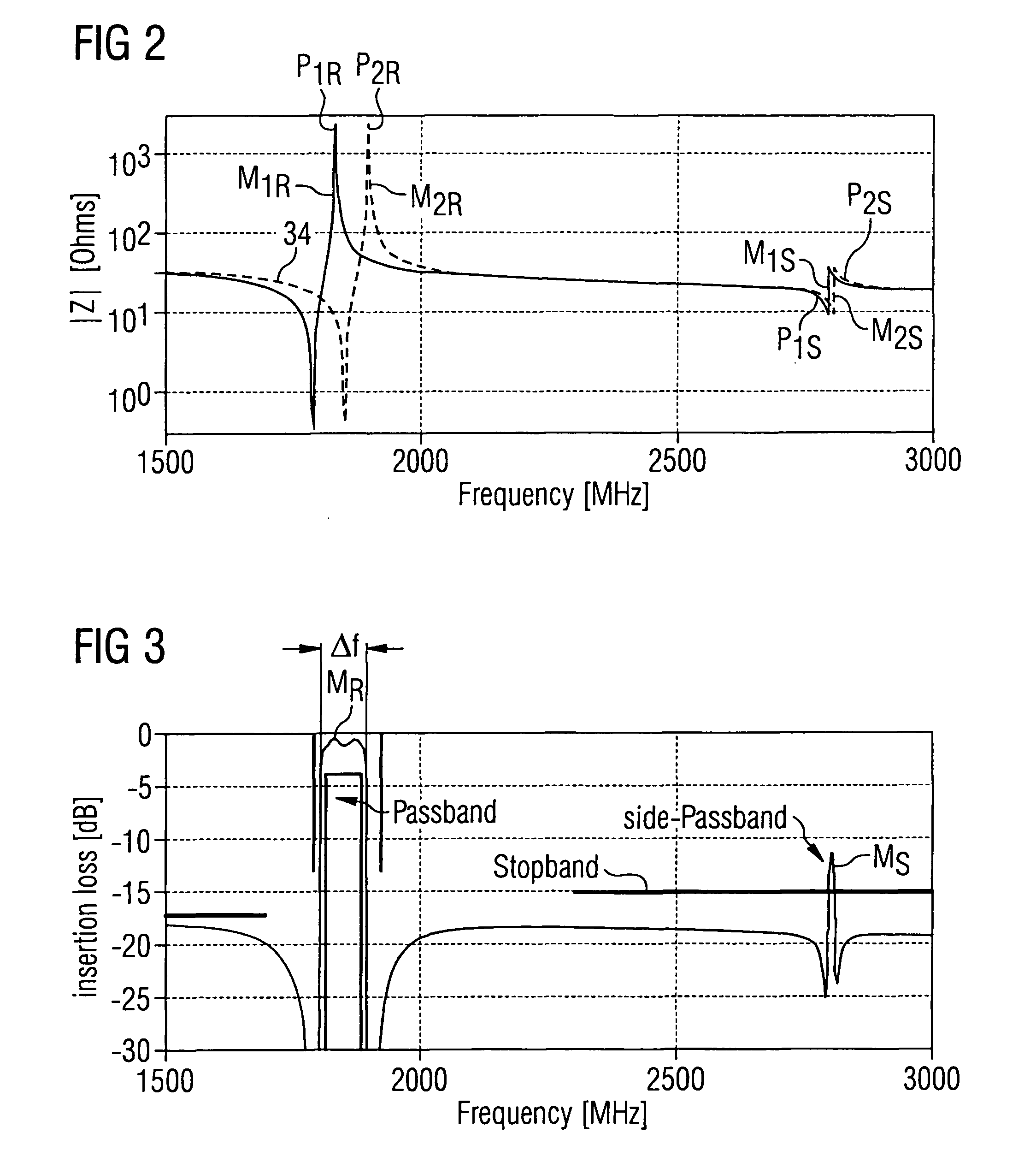
[0023] This bulk acoustic wave filter has the advantage, that the above mentioned overmodes particularly between the first and second order resonance frequencies are suppressed and no side-passband occurs in the stop band region of the required filter specification, particularly for specifications related to mobile phones or to other cellular, wireless or fiber-optic communications as well as in computer or computer related information exchange or information sharing systems.
[0034] This method has the additional advantage, that a short thinning step of the uppermost acoustic mirror layer is performed before the deposition of bottom electrodes takes place. This thinning is performed by etching just several Nanometres from the uppermost acoustic mirror layer in the region of the shunt resonator branch to suppress side-passband frequencies in the passband region. Actually the thinning range is between one-three-hundredth part to one-fiftieth part of one quarter of a wavelength at the acoustic resonance frequency. Thinning can easily be performed by wet etching, plasma etching, sputter etching or reactive ion etching. The region of the series resonator branch can be protected by a resist layer during the thinning process of the series resonator branch region.

Problems solved by technology

The overmode-detuning component may provide a mismatch of the thickness of the bottom electrodes beneath the piezo median plane.

Method used


Image

  • Bulk acoustic wave filter and method for eliminating unwanted side passbands
  • Bulk acoustic wave filter and method for eliminating unwanted side passbands
  • Bulk acoustic wave filter and method for eliminating unwanted side passbands

Examples


Embodiment Construction

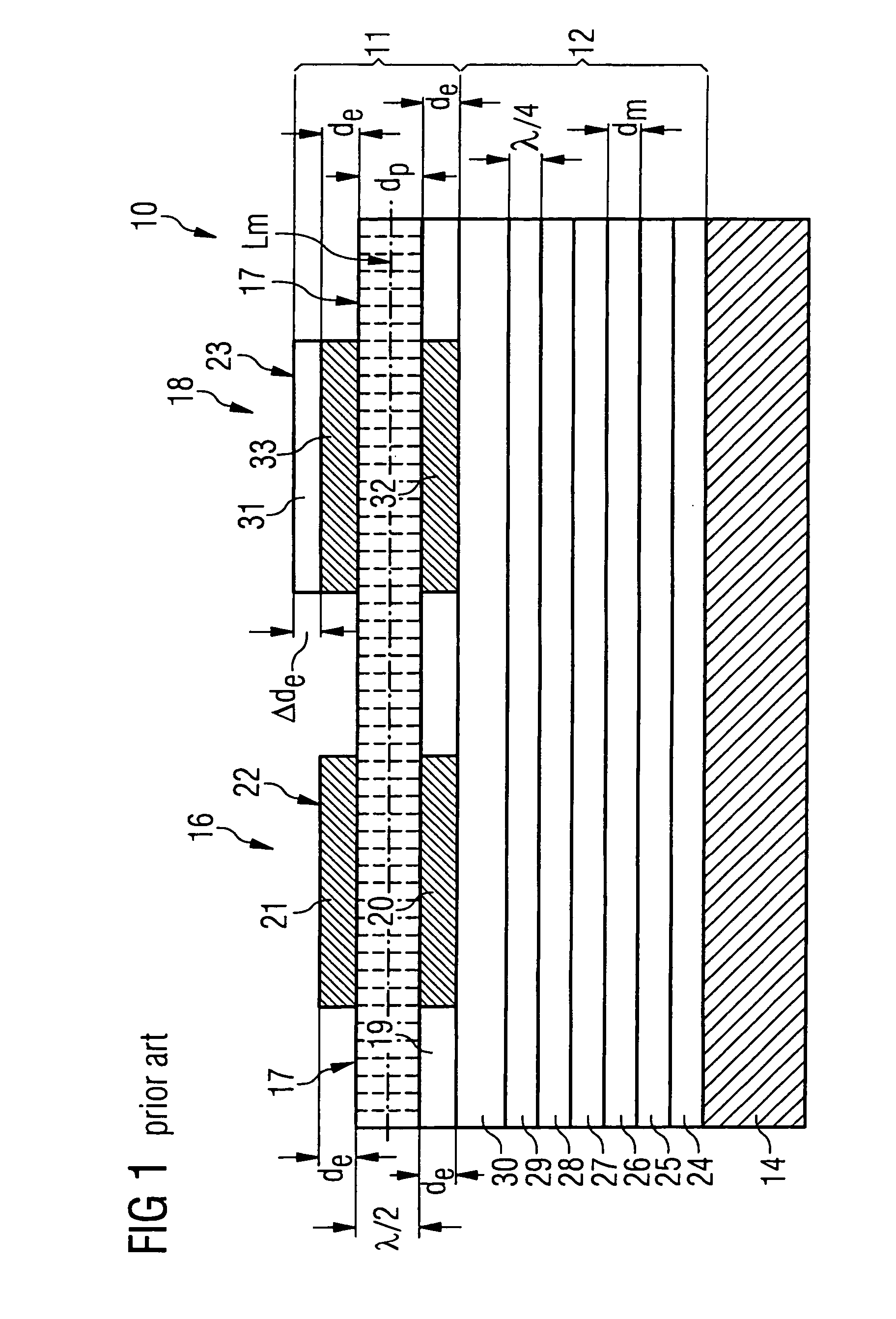
[0049]FIG. 1 shows a schematic of an acoustic mirror type thin film bulk acoustic wave resonator filter 10 according to the prior art described above and FIG. 2 shows an impedance plot of a series and a shunt bulk acoustic wave resonator 22, 23 forming said thin film bulk acoustic wave resonator filter 10 of FIG. 1. Furthermore FIG. 3 shows the transmission characteristics for said thin film bulk acoustic wave resonator filter of FIG. 1. As can be seen from FIG. 2 and FIG. 3, the acoustic mirror type thin film bulk acoustic wave resonator filter 10 shows an over-mode resonance forming a weak side-passband filter between the first order resonance frequency of the filter and the second harmonic resonance frequency. This side-passband of the filter potentially violates the stop band specifications required for various filter applications. Thus, there is a need for a new bulk acoustic wave resonator filter formed from a plurality of series bulk acoustic wave resonators and shunt bulk ac...


PUM


Abstract

A bulk acoustic wave (BAW) filter (40) is fabricated from thin film bulk acoustic wave resonators and a method eliminates unwanted side passbands. This BAW filter comprises a substrate (14) a resonator section (11) and an acoustic mirror section (12). Further it comprises a detuning component (31) positioned in the resonator section (11) to provide precise passband characteristics and an additional detuning component (41) in the acoustic mirror section (12) to suppress unwanted side-passband characteristics.

Description

PRIORITY [0001] This application claims priority to European Patent Application No. EP 04005574.1 which was filed Mar. 9, 2004. TECHNICAL FIELD OF THE INVENTION [0002] The present invention generally relates to a bulk acoustic wave filter such as lattice filters or ladder filters fabricated from solidly mounted thin film bulk acoustic wave resonators and a method for eliminating unwanted side passbands in the filter response. DESCRIPTION OF RELATED ART AND BACKGROUND OF THE INVENTION [0003] As shown in FIG. 1, a solidly mounted or acoustic mirror type thin film bulk acoustic wave resonator filter 10 of the state of the art includes a resonator section 11 based on a piezolayer 19 of piezoelectric material, such as ZnO or AlN, and includes an acoustic mirror 12, all mounted on a substrate 14 made for example, from glass. The thin film bulk acoustic wave resonators 16, 18 convert sound waves to electric signals, and vice versa, and can be used as a filter in electronic circuits because...

Claims


Application Information

Patent Timeline
Patent Type & Authority Applications(United States)
IPC IPC(8): H03H9/17H03H3/02H03H3/04H03H9/02H03H9/15H03H9/54H03H9/56H10N30/00
CPCH03H9/564H03H9/02118
Inventor AIGNER, ROBERTMARKSTEINER, STEPHAN
Owner AVAGO TECH INT SALES PTE LTD
Learn More