Circuit system for a battery electronic control unit
a circuit system and electronic control unit technology, applied in the field of circuit systems, can solve the problems of delay in the propagation of the signal, high cost of the insulator for insulating the propagated signal, and inefficiency of the use of a capacitor for propagating the digital signal having a value represented by binary levels in place of an analog, etc., and achieves the effect of low cost, large device area, and effective application
- Summary
- Abstract
- Description
- Claims
- Application Information
AI Technical Summary
Benefits of technology
Problems solved by technology
Method used
Image
Examples
first embodiment
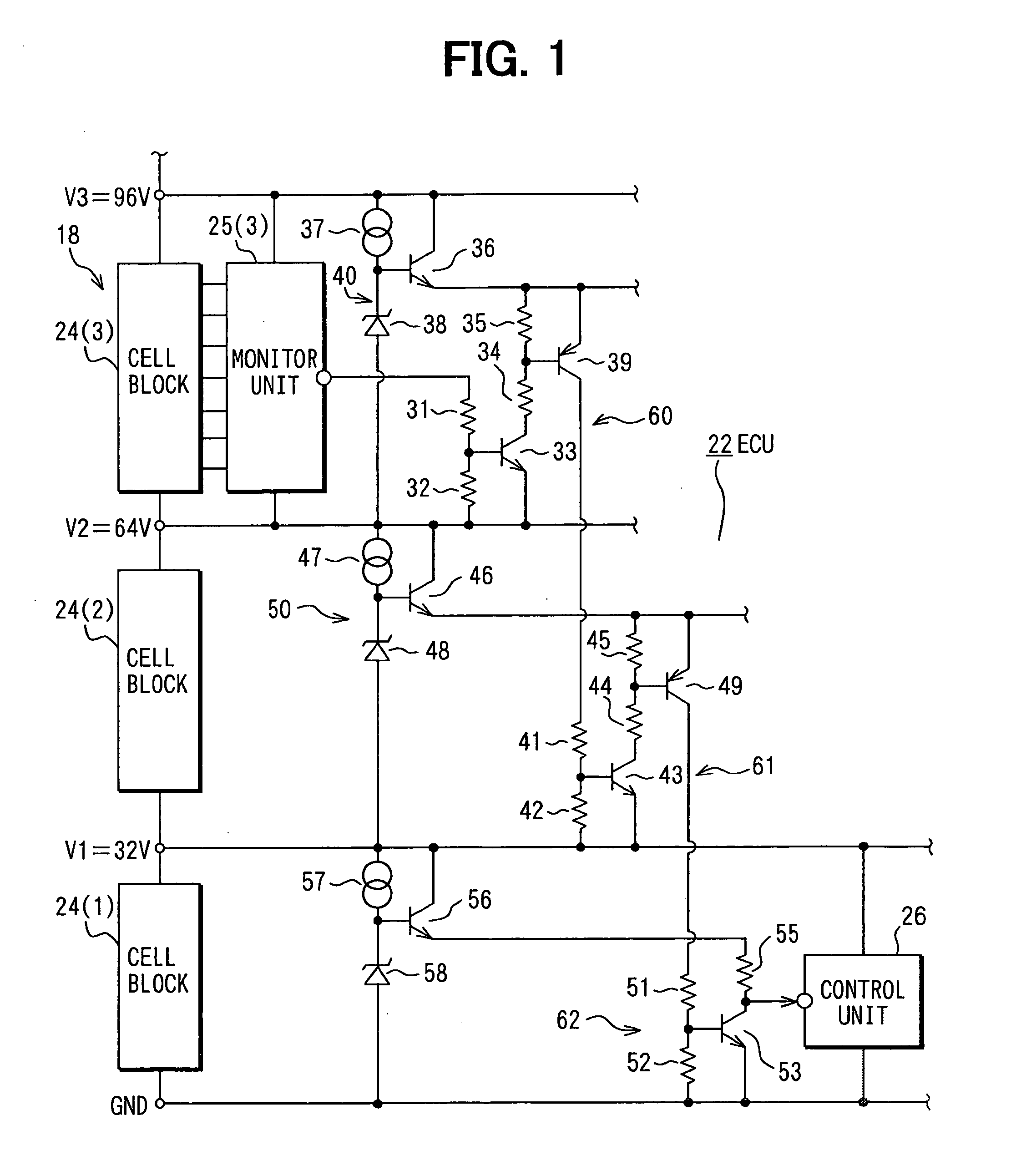
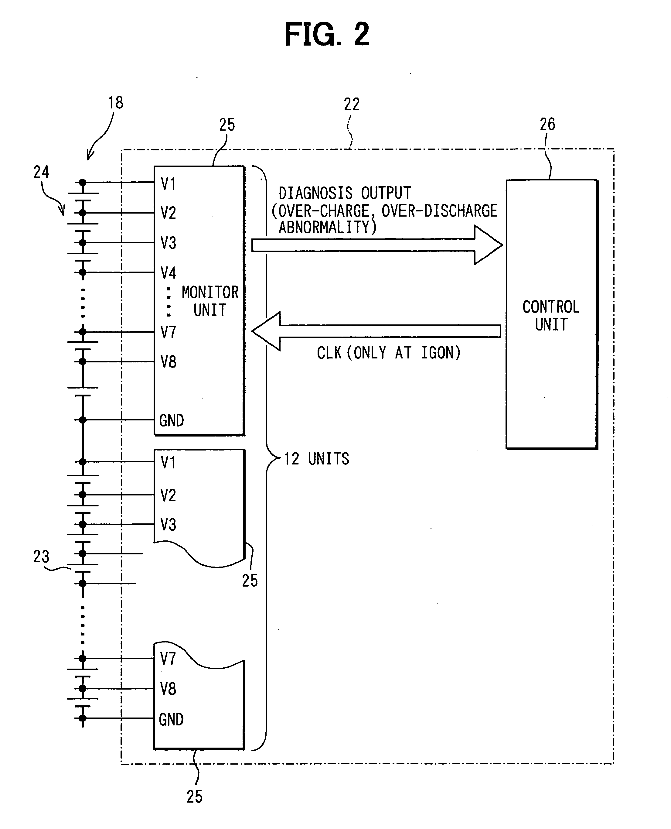
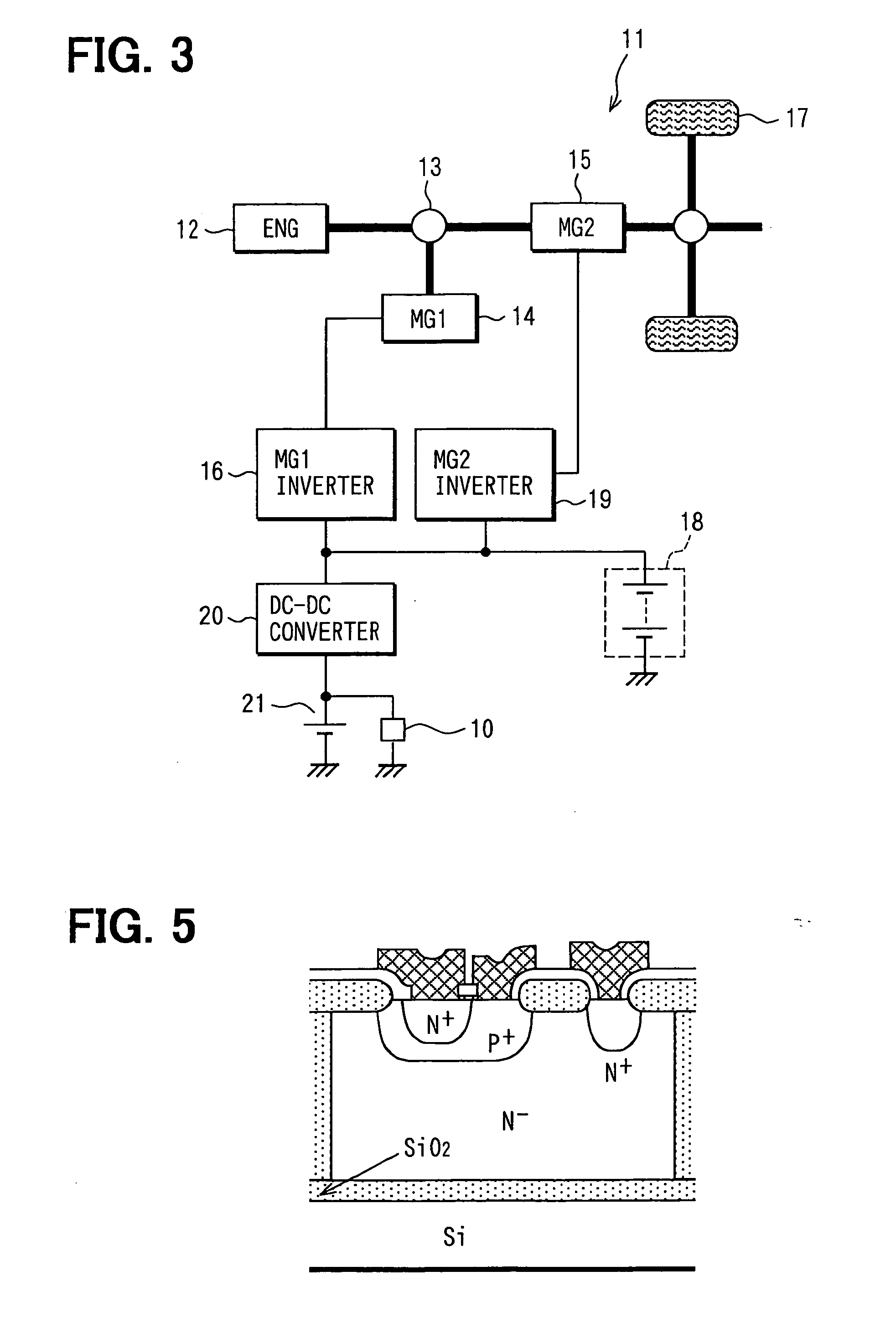
[0025] A first embodiment is explained by referring to FIGS. 1 to 3 for a case in which a circuit system is applied to a battery ECU for controlling a primary battery of a hybrid electric-powered vehicle. FIG. 3 is a diagram roughly showing the system configuration of a hybrid electric-powered vehicle (HEV) 11. In the HEV 11, a power division mechanism 13 divides a driving force generated by the engine (ENG) 12 into forces applied to motor / generators (MGs) 14 and 15. The MG 14 works mainly as a generator and adjusts the apportion of power through the power division mechanism 13. That is, the MG 14 executes the function of a transmission in addition to the function of a generator. An inverter 16 adjusts the output load of the MG 14. On the other hand, the MG 15 drives running wheels 17 of the HEV 11. The MG 15 has a configuration to drive the running wheels 17 in collaboration with the engine 12 in dependence on a control condition.
[0026] A main battery 18 supplies a voltage in the ...
second embodiment
[0051]FIG. 4 is a diagram showing a second embodiment. In this figure, circuit elements identical with their respective counterparts employed in the first embodiment are denoted by the same reference numerals as the counterparts and their descriptions are not repeated in order to avoid duplications. Only differences between the first and second embodiments are explained. The second embodiment implements a circuit configuration in which the control unit 26 on the low-voltage side outputs a signal to the cell-block monitor unit 25(3) on the high-voltage side. The figure shows only a portion of the battery ECU 22.
[0052] An output terminal of the control unit 26 is connected to the ground through a series circuit comprised of resistors 65 and 66. The junction point between the resistors 65 and 66 is connected to the base of an NPN transistor 67, which serves as a signal propagation transistor. The emitter of the transistor 67 is connected to the ground. On the other hand, the collector...
PUM
 Abstract
Description
Claims
Application Information
 - R&D
- Intellectual Property
- Life Sciences
- Materials
- Tech Scout
- Unparalleled Data Quality
- Higher Quality Content
- 60% Fewer Hallucinations
Browse by: Latest US Patents, China's latest patents, Technical Efficacy Thesaurus, Application Domain, Technology Topic, Popular Technical Reports.
© 2025 PatSnap. All rights reserved.Legal|Privacy policy|Modern Slavery Act Transparency Statement|Sitemap|About US| Contact US: help@patsnap.com


