
Ion beam monitoring arrangement

a technology of ion beam and monitoring arrangement, applied in the direction of oxygen/ozone/oxide/hydroxide, semiconductor/solid-state device testing/measurement, separation process, etc., can solve the problems of large aperture of faraday, large disadvantage, and large overlap of detectors with associated complexity and expens

Inactive Publication Date: 2005-09-01
APPLIED MATERIALS INC
View PDF25 Cites 64 Cited by
  • Summary
  • Abstract
  • Description
  • Claims
  • Application Information

AI Technical Summary

Benefits of technology

[0012] The arrangement described above is beneficial as it allows the cross-sectional profile of the ion beam to be measured using a Faraday or similar already provided as a beamstop. By occluding the ion beam by a progressively changing amount, i.e. moving the shield into the ion beam to cause progressive occlusion or moving the shield out of the ion beam to progressively uncover the ion beam, successive measurements may be taken and the ion beam profile calculated from changes in the successive measurements. This calculation may correspond to taking simple differences or may correspond to finding a derivative of the successive measurements.
[0013] Using the substrate support to provide the shield is particularly advantageous as it removes the need for providing a further component to the ion implanter. It also enjoys the benefit that the ion beam is occluded at a position at or close to the target position such that the ion beam profile at or close to the target position is obtained.
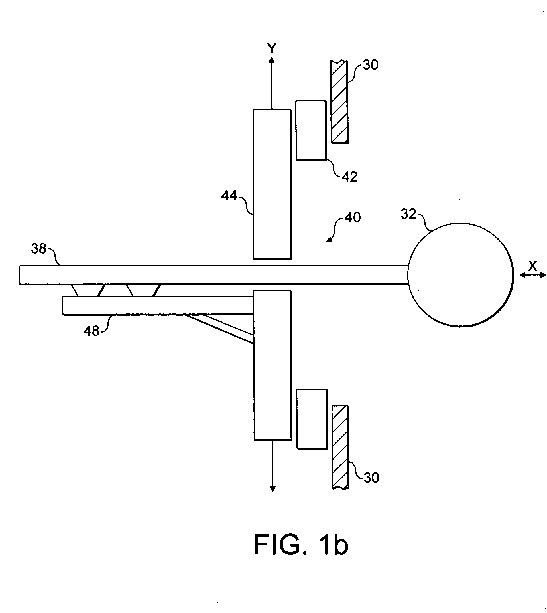
[0018] This arrangement allows successive portions of the ion beam flux to be measured and the ion beam profile determined therefrom. It requires only a minor adaptation of the substrate support and may use the Faraday that is often already present at the beamstop.
[0024] Measuring the ion beam flux along using an elongate slot detector improves statistics as it simply provides an average flux along the elongate direction rather than discretely sampling the flux at a plurality of point-like positions. For example, the detector could measure the ion beam flux along a line spanning the ion beam. Then, the total flux for successive strips across the ion beam could be measured to yield a cross-sectional profile.
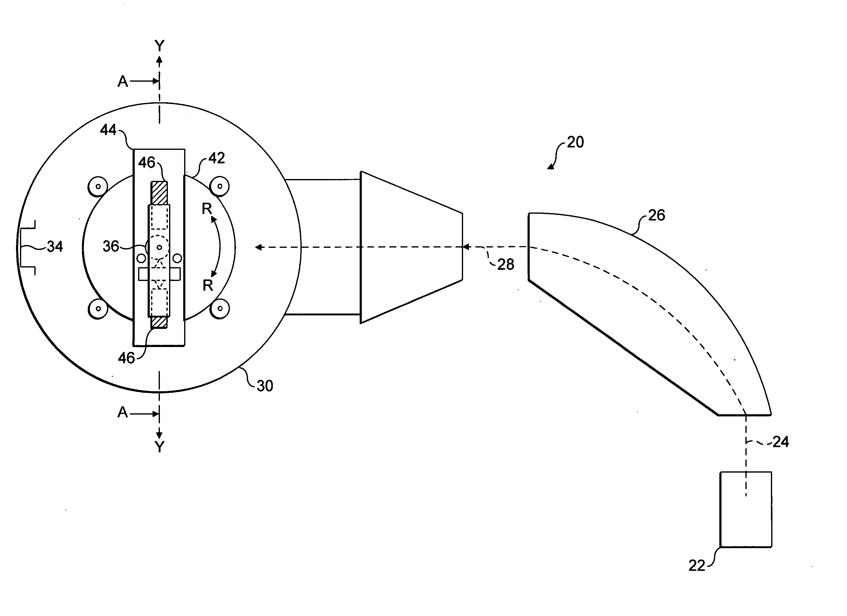
[0027] Variation in the angle of incidence of the ion beam about the Y axis is particularly important for control during high tilt implants. This corresponds to rotating the support arm to cause a high-tilt of the wafer (and hence larger angle of incidence of the ion beam) so that dopants can be implanted underneath high aspect ratio structures. (e.g. source extension halo implants). Any variation from a required beam angle about the Y-axis will change the extent to which the ions penetrate the structure, thereby changing the performance characteristics of the device being implanted.
[0042] The use of discrete detecting elements allows the determination of cross-sectional profiles in two directions at the same time. Preferably, the detecting elements are disposed in two adjacent, parallel lines in an alternating zig-zag pattern. This allows an array of detectors whose active detecting area may extend across a full width of the ion beam, as any dead areas (that may otherwise separate detecting elements disposed along a single line) to be overlapped across the two lines.

Problems solved by technology

This arrangement suffers from some disadvantages in certain applications.
Firstly, it requires a Faraday to be placed on the substrate holder.
Moreover, many ion implanters comprise a beamstop placed downstream of the substrate holder that includes a Faraday thereby leading to duplication of detectors with associated complexity and expense.
Secondly, the entrance aperture of the Faraday is much smaller than the ion beam.
As a result, the aperture can collect only a small signal leading to noisy data or long acquisition times. The total data collection is very slow as, in addition to lengthy acquisition times needed to produce an acceptable signal to noise ratio, the ion beam must be sampled at many points over a two-dimensional grid to provide a profile.
However, careful alignment with the ion beam must be performed for the aperture to pass through the centre of the ion beam, otherwise the full width of the ion beam will not be measured.

Method used


Image

  • Ion beam monitoring arrangement
  • Ion beam monitoring arrangement
  • Ion beam monitoring arrangement

Examples


first embodiment

[0085] It is convenient to use the substrate support to move the shield 58 as it already has the ability to move along the X- and Y-coordinate directions. A first embodiment is shown in FIG. 4 where the support arm 38 itself is used as a shield 58. In this embodiment, the support arm 38 has a flat lower edge that extends along the X-coordinate direction. Accordingly, the chuck 36 can be driven across the process chamber 30 past the ion beam 28 such that the flat lower edge of the support arm 38 is located above the ion beam 28. In this arrangement, passage of the ion beam 28 to the beamstop 34 is unobstructed and the Faraday 34 measures the total ion beam flux. The support arm 38 is then driven downwards into the ion beam 28 such that the flat lower edge progressively occludes the ion beam 28.

[0086] The ion beam 28 striking the support arm 38 will cause localised heating and also possibly ablation of material. In either event, the result is the possibility of contamination of a wafe...

second embodiment

[0093] While the embodiment of FIG. 4 is particularly simple, it allows only the profile of the ion beam 28 in the Y-coordinate direction to be determined. A second embodiment is shown in FIG. 5 that allows the profile in both X- and Y-coordinate directions to be measured. The chuck 36 is modified to include straight edges 60 provided at its outermost and bottommost extremes such that they extend along the Y- and X-coordinate directions respectively. The edges 60 may be covered or coated with semiconductor material or graphite (or similar) to reduce contamination problems.

[0094] The edges 60 may be driven into the ion beam 28 from either side of the ion beam 28 or from above the ion beam 28 to cause progressive occlusion. As per the embodiment of FIG. 4, the controller records the change in measured ion flux along with the position of the chuck 36 and determines the ion flux profile therefrom. Driving the chuck 36 vertically will allow the profile in the Y-coordinate direction to be...


PUM

PropertyMeasurementUnit
Depthaaaaaaaaaa
Elongationaaaaaaaaaa

Abstract

This invention relates to an ion beam monitoring arrangement for use in an ion implanter where it is desirable to monitor the flux and / or a cross-sectional profile of the ion beam used for implantation. It is often desirable to measure the flux and / or cross-sectional profile of an ion beam in an ion implanter in order to improve control of ion implantation of a semiconductor wafer or similar. The present invention describes adapting the wafer holder to allow such beam profiling to be performed. The substrate holder may be used progressively to occlude the ion beam from a downstream flux monitor or a flux monitor may be located on the wafer holder that is provided with a slit entrance aperture.

Description

FIELD OF THE INVENTION [0001] This invention relates to an ion beam monitoring arrangement for use in an ion implanter where it is desirable to monitor the flux and / or a cross-sectional profile of the ion beam used for implantation. This invention also relates to an ion implanter process chamber and an ion implanter including such an ion beam monitoring arrangement, and to a method of monitoring an ion beam in an ion implanter. BACKGROUND OF THE INVENTION [0002] Ion implanters are well known and generally conform to a common design as follows. An ion source produces a mixed beam of ions from a precursor gas or the like. Only ions of a particular species are usually required for implantation in a substrate, for example a particular dopant for implantation in a semiconductor wafer. The required ions are selected from the mixed ion beam using a mass-analysing magnet in association with a mass-resolving slit. Hence, an ion beam containing almost exclusively the required ion species emer...

Claims


Application Information

Patent Timeline
IPC IPC(8): H01L21/265B05D1/00C23C14/00C23C16/00H01J27/00H01J37/244H01J37/304H01J37/317H01L21/425H01L21/66
CPCH01J2237/30455H01J37/3171H01J37/304H01J2237/31703H01J37/244H01J37/3172B01D53/0407B01D2259/40005C01B13/0259
Inventor MURRELL, ADRIANHARRISON, BERNARD F.EDWARDS, PETERKINDERSLEY, PETERMITCHELL, ROBERTSMICK, THEODORERYDING, GEOFFREYFARLEY, MARVINSAKASE, TAKAO
Owner APPLIED MATERIALS INC
Learn More