
Method of forming a hydrophobic coating layer on a surface of a nozzle plate for an ink-jet printhead

a technology of inkjet printhead and coating layer, which is applied in the field of hydrophobic coating layer on the surface of a nozzle plate for inkjet printhead, can solve the problems of deteriorating ink droplet ejection performance, easy contamination of the peripheral nozzle , easy contamination of ink, so as to enhance the ejection performance of ink droplets and improve print quality

Inactive Publication Date: 2005-09-01
SAMSUNG ELECTRO MECHANICS CO LTD
View PDF20 Cites 12 Cited by
  • Summary
  • Abstract
  • Description
  • Claims
  • Application Information

AI Technical Summary

Benefits of technology

The present invention provides a method of forming a hydrophobic coating layer on a surface of a nozzle plate for an ink-jet printhead. This method selectively forms a uniform hydrophobic coating layer only on an outer surface of a nozzle plate, improving the ejection performance of ink droplets through a nozzle and improving print quality. The method is simplified compared to conventional methods and uses a sulfur compound-containing solution to form the hydrophobic coating layer. The nozzle plate may be a silicon wafer or a glass substrate. The metal layer may be made of gold, silver, copper, or indium, with gold being the preferred metal. The material layer may be a silicon oxide layer or a silicon nitride layer. Etching the material layer may be performed using reactive ion etching or plasma-enhanced chemical vapor deposition. The sulfur compound may be a thiol compound.

Problems solved by technology

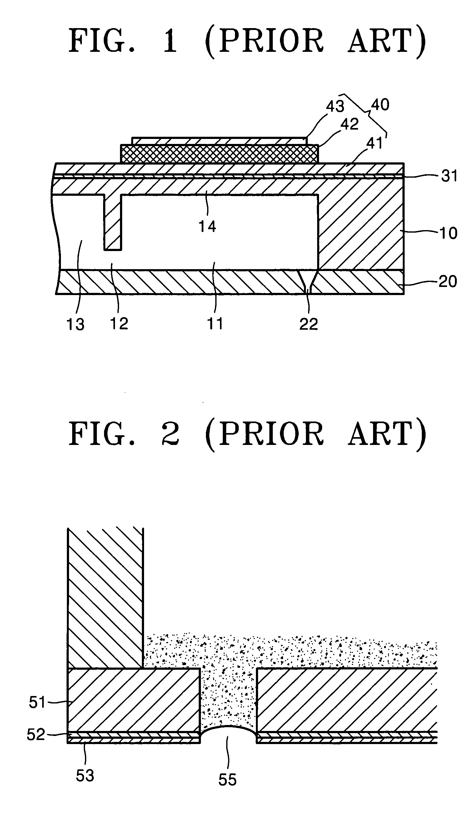
Resultantly, when the sulfur compound layer 53, which is a hydrophobic coating layer, is formed poorly, a periphery of the nozzle 55 may be easily contaminated by ink and ink droplet ejection performance may deteriorate due to low ejection speed or non-uniform ejection direction.
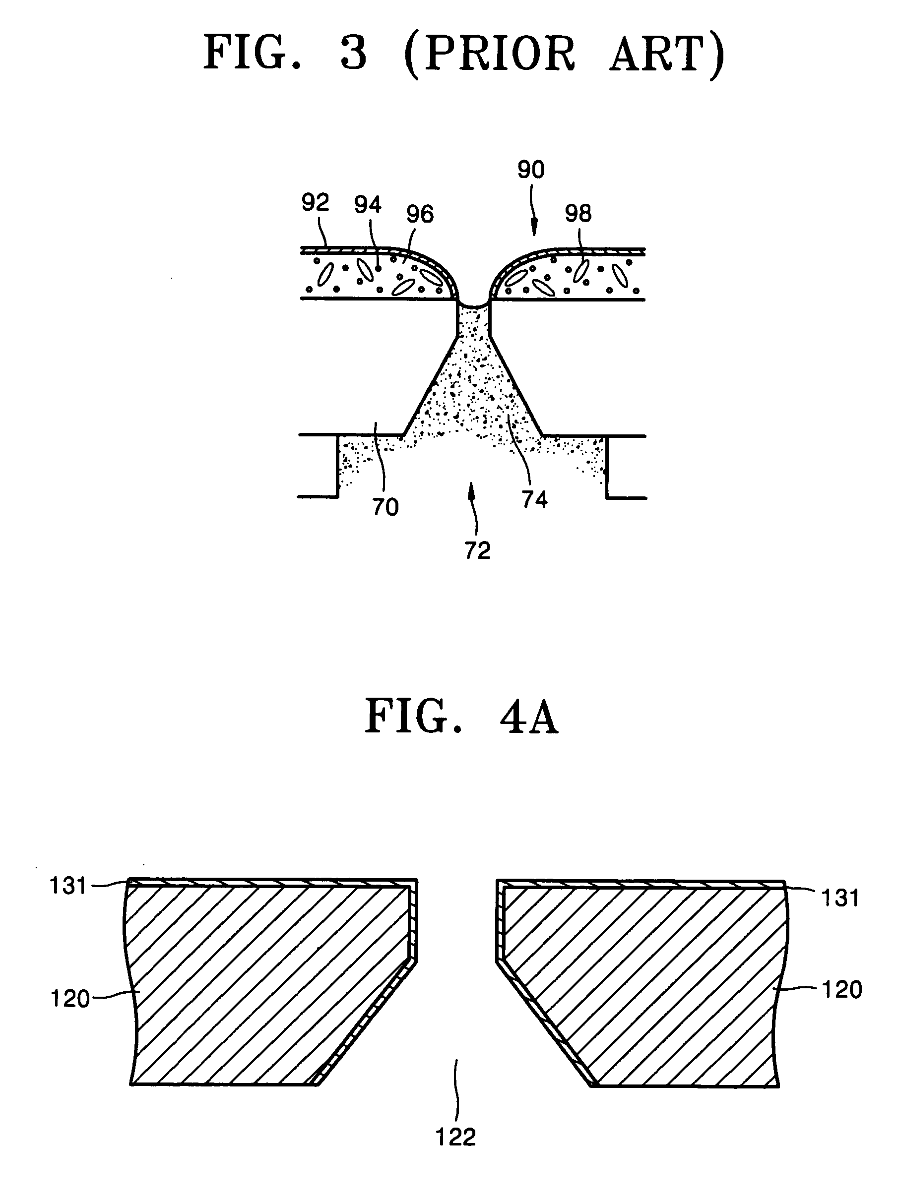
However, this conventional method involves a cumbersome process to remove the polymer resin 74 filled in the nozzle 72.
However, this method requires a complicated apparatus and a difficult process, which renders industrial application difficult.

Method used


Image

  • Method of forming a hydrophobic coating layer on a surface of a nozzle plate for an ink-jet printhead
  • Method of forming a hydrophobic coating layer on a surface of a nozzle plate for an ink-jet printhead
  • Method of forming a hydrophobic coating layer on a surface of a nozzle plate for an ink-jet printhead

Examples


Embodiment Construction

[0035] Korean Patent Application No. 10-2004-0013562, filed on Feb. 27, 2004, in the Korean Intellectual Property Office, and entitled: “Method of Forming a Hydrophobic Coating Layer on a Surface of a Nozzle Plate for an Ink-jet Printhead,” is incorporated by reference herein in its entirety.

[0036] The present invention will now be described more fully hereinafter with reference to the accompanying drawings, in which exemplary embodiments of the invention are shown. The invention may, however, be embodied in different forms and should not be construed as limited to the embodiments set forth herein. Rather, these embodiments are provided so that this disclosure will be thorough and complete, and will fully convey the scope of the invention to those skilled in the art. In the figures, the dimensions of elements, layers and regions are exaggerated for clarity of illustration. It will also be understood that when a layer is referred to as being “on” another layer or substrate, it can b...


PUM

PropertyMeasurementUnit
hydrophobicaaaaaaaaaa
volumeaaaaaaaaaa
pressureaaaaaaaaaa

Abstract

A method of forming a hydrophobic coating layer on a surface of a nozzle plate for an ink-jet printhead includes preparing a nozzle plate having a nozzle, forming a metal layer on a surface of the nozzle plate, forming a material layer covering the metal layer, selectively etching the material layer to expose a portion of the metal layer formed on an outer surface of the nozzle plate, and forming the hydrophobic coating layer of a sulfur compound on the exposed portion of the metal layer by dipping the nozzle plate in a sulfur compound-containing solution.

Description

BACKGROUND OF THE INVENTION [0001] 1. Field of the Invention [0002] The present invention relates to an ink-jet printhead. More particularly, the present invention relates to a method of forming a hydrophobic coating layer on a surface of a nozzle plate for an ink-jet printhead. [0003] 2. Description of the Related Art [0004] Generally, an ink-jet printhead is a device that ejects small volume ink droplets at desired positions on a recording medium to print a desired color image. Ink-jet printheads are generally categorized into two types depending on which ink ejection mechanism is used. A first type is a thermal ink-jet printhead, in which ink is heated to form ink bubbles and the expansive force of the bubbles causes ink droplets to be ejected. A second type is a piezoelectric ink-jet printhead, in which a piezoelectric crystal is deformed to exert pressure on ink causing ink droplets to be ejected. [0005]FIG. 1 illustrates a cross-sectional view of a conventional piezoelectric i...

Claims


Application Information

Patent Timeline
Patent Type & Authority Applications(United States)
IPC IPC(8): B41J2/16B41J2/135
CPCB41J2/1606B41J2/162B41J2/1646B41J2/1642B41J2/1628
Inventor LIM, SEUNG-MOYOU, KYUNG-HEECHUNG, JAE-WOO
Owner SAMSUNG ELECTRO MECHANICS CO LTD
Learn More