Automobile injection mold
A technology for injection molds and automobiles, used in household appliances, other household appliances, household components, etc., can solve the problems of difficult demoulding, easily damaged products, affecting the quality of injection molded products, etc., to reduce damage, ensure product quality, and improve The effect of the ejection effect
- Summary
- Abstract
- Description
- Claims
- Application Information
AI Technical Summary
Problems solved by technology
Method used
Image
Examples
specific Embodiment approach 1
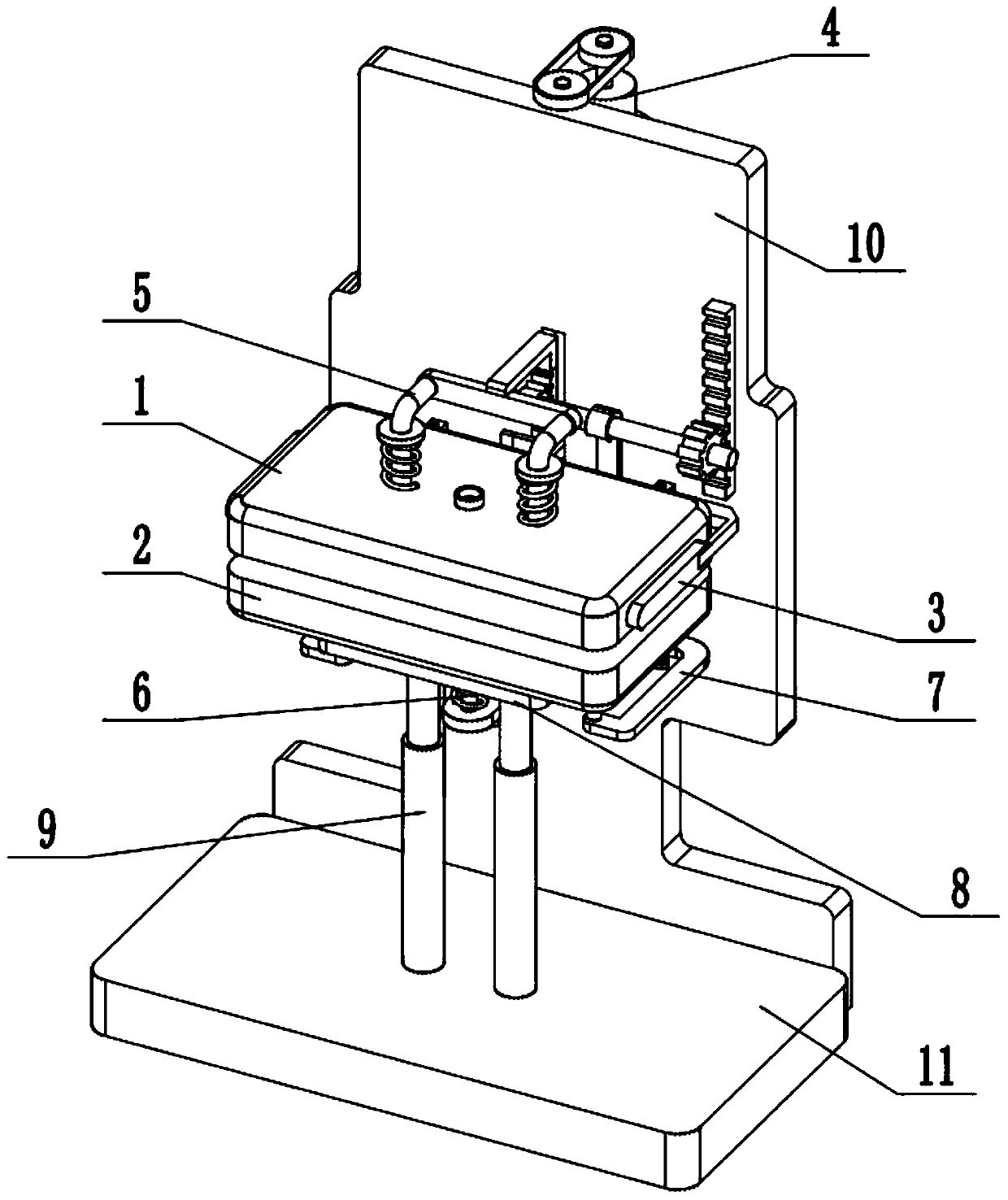
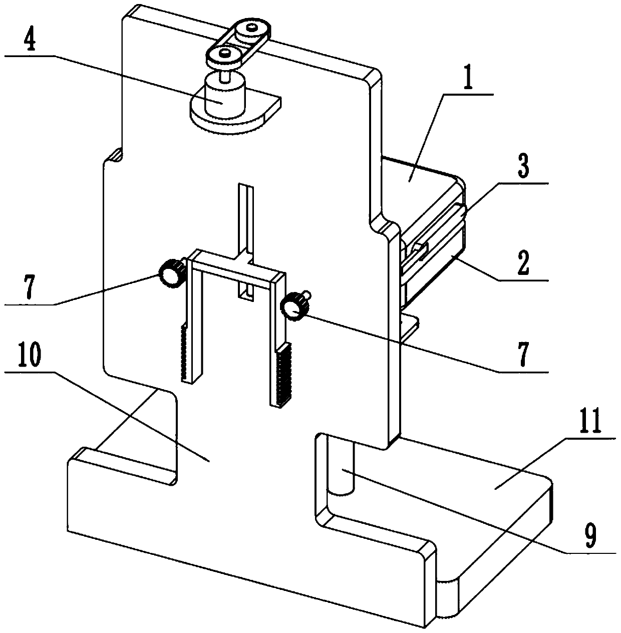
[0029] Such as Figure 1-11As shown, a kind of automobile injection mold, comprises movable mold core 1, fixed mold core 2, movable frame 3, opening and closing mold controller 4, upper micro-top demoulding device 5, lower micro-top demoulding device 6, ejector 7. Supporting plate 8, column 9, backboard 10 and base 11, the moving model core 1 is fixed on the front end of movable frame 3, the middle part of movable frame 3 is connected on the backboard 10, and the rear end of movable frame 3 is connected by transmission Two ejectors 7; the middle parts of the two ejectors 7 are connected to the back plate 10, and the front ends of the two ejectors 7 are respectively sealed and slidably fitted to the two ends of the bottom surface of the fixed mold core 2; the opening and closing mold The controller 4 is fixed on the back plate 10, and the mold opening and closing controller 4 is connected to the movable frame 3 through transmission; The middle part of the stripper 5 is fixed o...
specific Embodiment approach 2
[0031] Such as Figure 1-11 As shown, the mold opening and closing controller 4 includes a servo motor 4-1 and a drive pulley 4-2; the servo motor 4-1 is fixed on the backplane 10 through a motor base, and the output shaft of the servo motor 4-1 The upper part is fixedly connected to the driving pulley 4-2; the driving pulley 4-2 is connected to the movable frame 3 through a belt transmission. When the servo motor 4-1 works, it can drive the driving pulley 4-2 to rotate, and then control the work of the movable frame 3 through the driving pulley 4-2.
specific Embodiment approach 3
[0033] Such as Figure 1-11 As shown, the movable frame 3 includes a driven pulley 3-1, a lead screw 3-2, a lifting slide 3-3, a mounting frame 3-4, a door-shaped linkage plate 3-5 and a transmission rack 3-6; The drive pulley 4-2 is connected to the passive pulley 3-1 fixed on the top of the lead screw 3-2 through a belt transmission, and the bottom end of the lead screw 3-2 rotates and is connected to the lower end inside the vertical chute on the backboard 10. , the lifting slide plate 3-3 is slidably fitted in the vertical chute, and the lifting slide plate 3-3 is threadedly connected to the lead screw 3-2; Door-shaped linkage plate 3-5; the moving model core 1 is fixedly connected to the mounting frame 3-4; the left and right ends of the door-shaped linkage plate 3-5 are respectively fixedly connected to a transmission rack 3-6, two transmission racks The teeth on the racks 3-6 are all set towards the outside; the outer sides of the two transmission racks 3-6 are meshed ...
PUM
 Abstract
Description
Claims
Application Information
 - R&D
- Intellectual Property
- Life Sciences
- Materials
- Tech Scout
- Unparalleled Data Quality
- Higher Quality Content
- 60% Fewer Hallucinations
Browse by: Latest US Patents, China's latest patents, Technical Efficacy Thesaurus, Application Domain, Technology Topic, Popular Technical Reports.
© 2025 PatSnap. All rights reserved.Legal|Privacy policy|Modern Slavery Act Transparency Statement|Sitemap|About US| Contact US: help@patsnap.com


