Automatic time constant adjustment circuit
a technology of automatic adjustment and time constant, applied in the field of automatic time constant adjustment circuit, can solve the problems of large error, time-consuming adjustment, and large product of resistance and capacitance error of about 20%, so as to reduce the error in time constant and improve accuracy.
- Summary
- Abstract
- Description
- Claims
- Application Information
AI Technical Summary
Benefits of technology
Problems solved by technology
Method used
Image

Examples
first embodiment
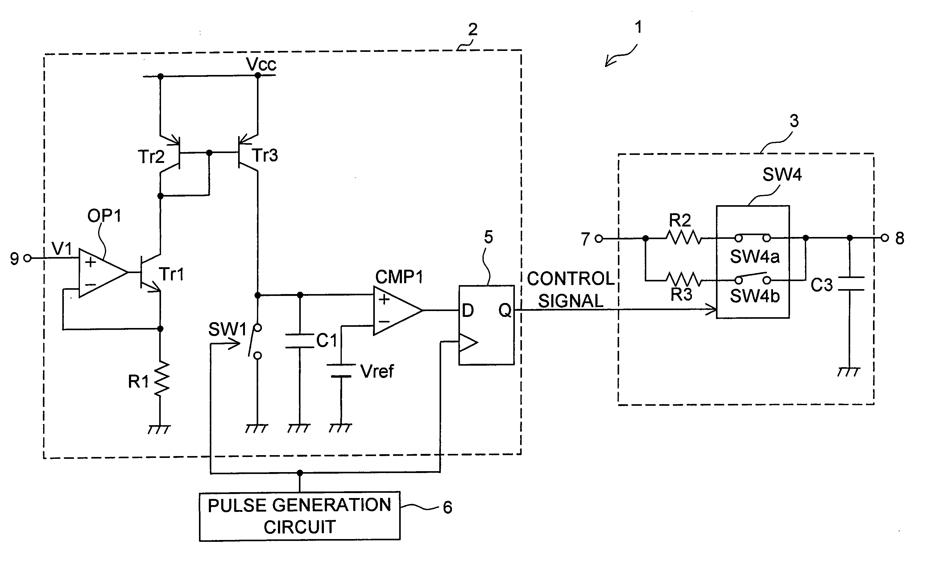
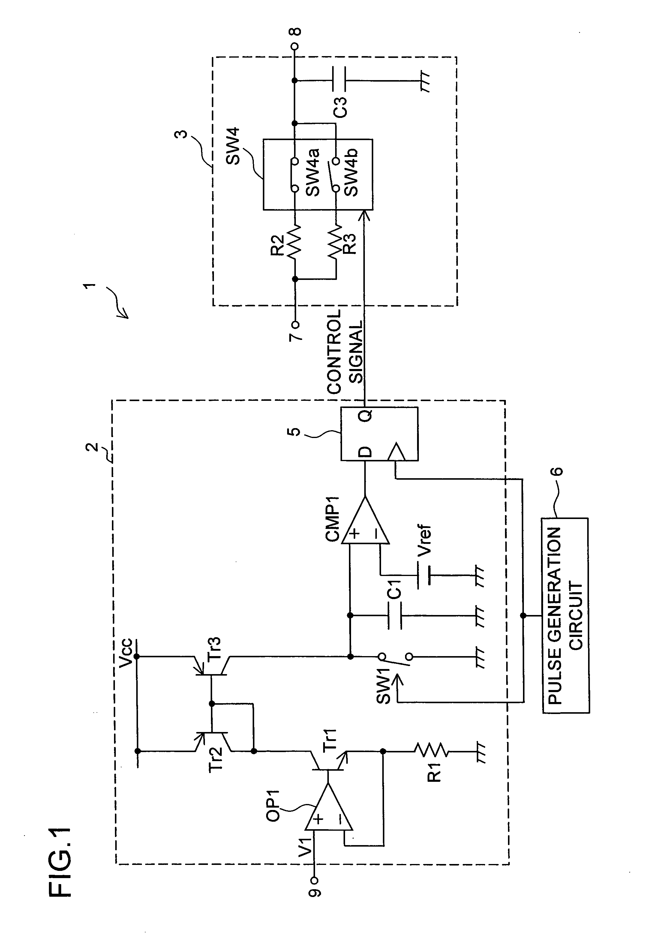
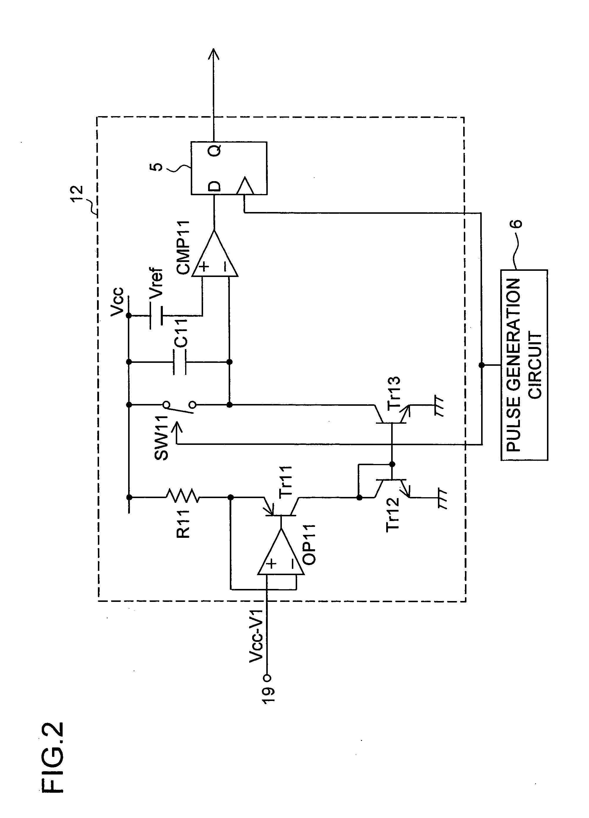
[0032] The automatic time constant adjustment circuit of a first embodiment of the invention will be described below with reference to FIGS. 1 and 2. FIG. 1 is a circuit diagram showing the configuration of the automatic time constant adjustment circuit 1 of the first embodiment. The automatic time constant adjustment circuit 1 is composed of: an error detection circuit 2 that detects an resistance / capacitance error resulting from a variation attributable to an IC process, and that then outputs a control signal corresponding to the resistance / capacitance error; a variable time constant circuit 3 of which the time constant is variable; and a pulse generation circuit 6 that feeds a pulse voltage to the error detection circuit 2.
[0033] Here, a “resistance / capacitance error” denotes the value calculated, in a case where a resistor and a capacitor are formed by IC processes on a semiconductor substrate, by subtracting from the “product of the resistance and capacitance of the actually f...
second embodiment
[0068] Next, the automatic time constant adjustment circuit of a second embodiment of the invention will be described below with reference to FIG. 3. FIG. 3 shows, out of the overall circuit configuration of the automatic time constant adjustment circuit of the second embodiment, the part that constitutes a variable time constant circuit 23. In the second embodiment, the error detection circuit (the error detection circuit 2 or 12) and the pulse generation circuit 6 are configured in the same manner as in the first embodiment, and therefore these are not shown in FIG. 3 nor described any further below. The following description of the second embodiment assumes the use of the error detection circuit 2 (see FIG. 1) in combination with the variable time constant circuit 23, but it is of course possible to use instead the error detection circuit 12 (see FIG. 2) in combination with the variable time constant circuit 23.
[0069] A terminal 27 is connected to one end of a capacitor C22 and ...
third embodiment
[0079] Next, the automatic time constant adjustment circuit of a third embodiment of the invention will be described with reference to FIG. 4. FIG. 4 is a circuit diagram showing the configuration of the automatic time constant adjustment circuit 31 of the third embodiment. In FIG. 4, such circuit elements and signals as find their counterparts in FIG. 1 are identified with common reference numerals and symbols, and their explanations will not be repeated.
Configuration of the Error Detection Circuit 32
[0080] The error detection circuit 32 shown in FIG. 4 differs from the error detection circuit 2 shown in FIG. 1 in the following respects. The non-inverting input terminal (+) of a comparator CMP2, which receives a reference voltage Vref2 at the inverting input terminal (−) thereof, is connected to the non-inverting input terminal (+) of the comparator CMP1. The voltage fed to the inverting input terminal (−) of the comparator CMP1 is a reference voltage Vrefl. Instead of the D flip...
PUM
 Abstract
Description
Claims
Application Information
 - R&D
- Intellectual Property
- Life Sciences
- Materials
- Tech Scout
- Unparalleled Data Quality
- Higher Quality Content
- 60% Fewer Hallucinations
Browse by: Latest US Patents, China's latest patents, Technical Efficacy Thesaurus, Application Domain, Technology Topic, Popular Technical Reports.
© 2025 PatSnap. All rights reserved.Legal|Privacy policy|Modern Slavery Act Transparency Statement|Sitemap|About US| Contact US: help@patsnap.com