Jettable compositions

Active Publication Date: 2005-08-04
3D SYST INC +1
View PDF5 Cites 231 Cited by
  • Summary
  • Abstract
  • Description
  • Claims
  • Application Information

AI Technical Summary

Benefits of technology

[0108] Importantly, stabilisers for the whole composition should be present which prevent the long-term corrosion of the piezo print head.
[0109] If necessary, the resin composition according to the present invention may contain other materials in suitable amounts, as far as the effect of the present invention is not adversely affected. Examples of such materials include radical-polymerizable organ

Problems solved by technology

Early jet deposition heads were based on bubblejet technology and were limited to using aqueous inks.
Aqueous inks require time to dry and this factor limits their application; also, the need to provide for space where the drying takes place limits the maximum rate at which printing can take place.
However, there are several constraints on the types of compositions that can be used in jet deposition.
Unfortunately many curable compositions that can provide desirable final properties also have high viscosities and are therefore difficult to jet.
However, wax is not a robust material and the phase change inks have very limited application.
There have been proposals to incorporate a curable material into a wax (see for example U.S. Pat. No. 5,855,836), but this is of only lim

Method used


Image

  • Jettable compositions
  • Jettable compositions
  • Jettable compositions

Examples


examples 9-12

3D Printing Application Using Powders as Receiving Substrates

[0142] Mechanical test specimens were built using the following procedure. [0143] 1. A layer of the appropriate powder (500 μm) was spread on a metal substrate. [0144] 2. The appropriate resin was jetted onto the powder using a Microfab single jet head heated to 70° C., in a pattern consisting of lines spaced laterally by 250 μm, at a density given below. The pattern was then cured by exposure to TV light (4 W, WVA, 120 mJ / cm2) [0145] 3. A further layer of powder (300 μm) was spread over the previous layer, and step 2 repeated. [0146] 4. Step 4 was repeated 3 times. The article was removed from the free powder, and tensile properties were measured using Stable Micro Systems TA-HDi Texture Analyser, test speed 0.08 mm / s, grip distance 55 mm.

[0147] Four tests were carried out (Examples 9 to 12) and the parameters of the test and the properties of the resulting samples are shown in Table 5.

TABLE 5TensileElongationDroplets...

example 13

Jettable Composition:

[0153] The following components were mixed by tumbling in a glass bottle for 2 hours, under yellow light conditions.

UVR610550gUVR600035gCAP30110gUVI 69765gStabilizer BDMA0.1g

[0154] The liquid resin had following properties: [0155] Viscosity (Brookfield viscometer / rate 100 rpm): 70 mPas / 25° C.; 8 mPas / 70° C. [0156] Surface tension: 42 dynes / cm

[0157] The above UV curable composition was deposited on a test substrate with a specific pattern using a single piezoelectric jet printer head from Microfab Technologies Inc, Plano, Tex., USA. The printhead was heated to 70° C. under the following parameters: [0158] Printhead Scan rate was 20 mm / second [0159] The drop density was 150 droplets / mm with a line space of 0.25 mm

example 14

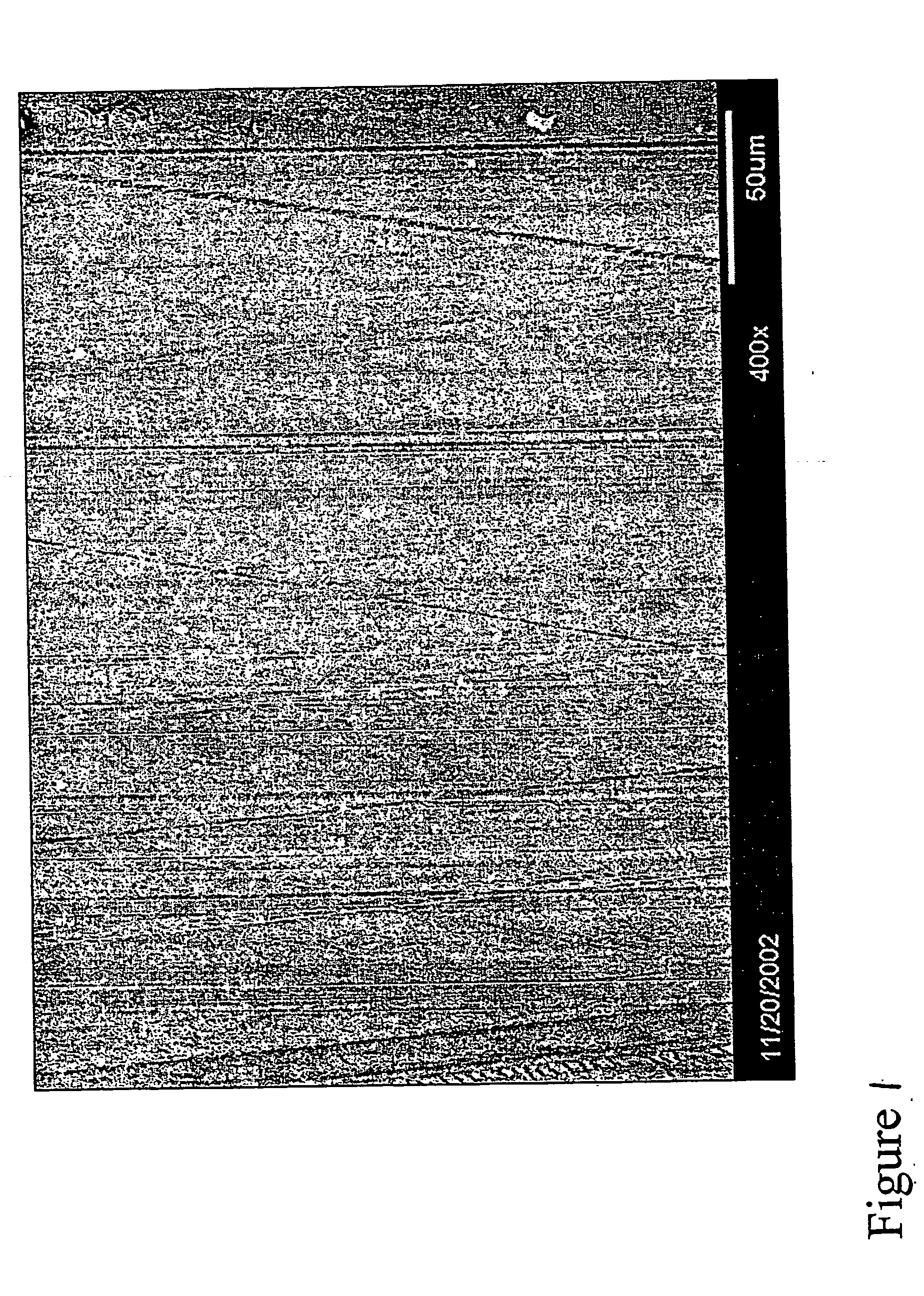
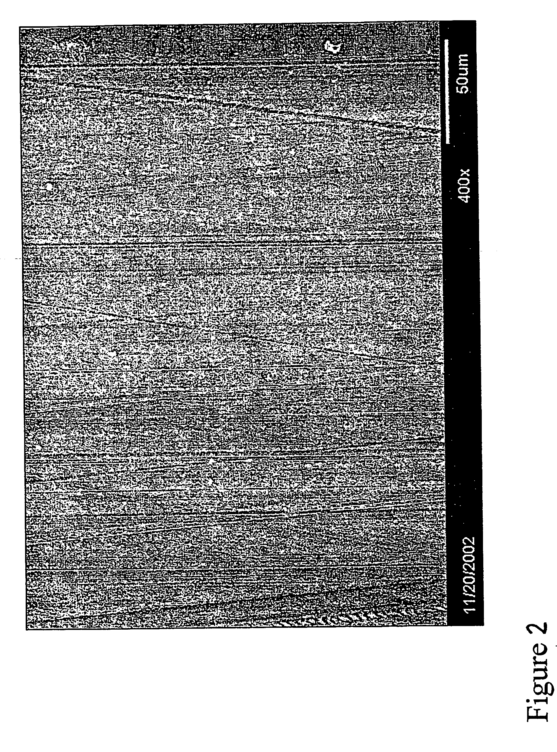
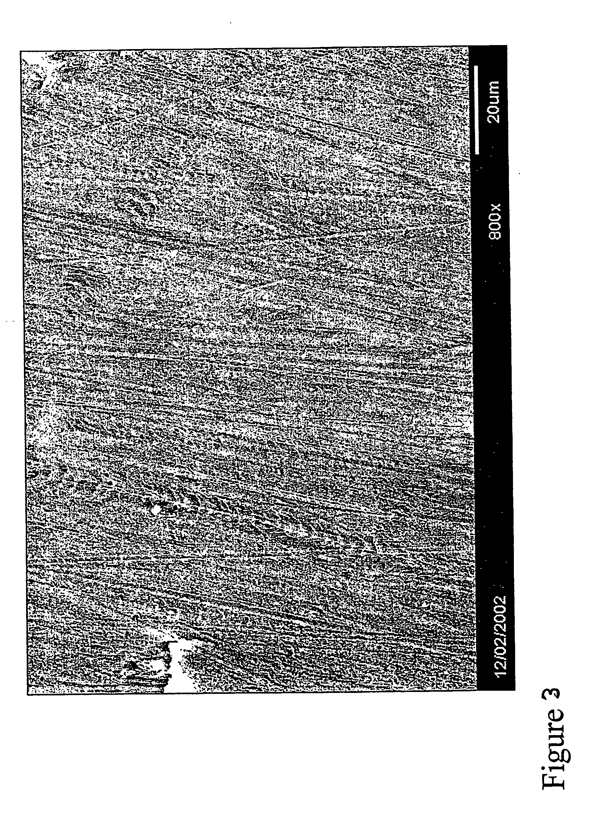
[0160] Using the jettable toughened, stabilised composition of Example 13, two overlapping lines of droplets were deposited as set out in Example 13 onto a polypropylene carrier sheet at a drop density of 150 droplets / mm with a line space of 0.25 mm and UV cured under a 4 W UVA lamp with a curing energy of 120 mJ / cm2. Where a two layer deposit is formed, the second layer is deposited on the first layer and cured under identical conditions.

[0161] A one-layer specimen and a two-layer specimen were examined using the SIEM method (Speckle Interferometry with Electron Microscopy). SIEM is a micro / nano-scale technique that is able to perform full field displacement mapping over a region of only a few microns in diameter. First, a random speckle pattern of nanoscale gold particles, which serve as displacement gauges, is deposited on a specimen surface. The specimen is placed under a load and the nanospeckle patterns before and after deformation of the specimen as a result of the load are ...


PUM

PropertyMeasurementUnit
Temperatureaaaaaaaaaa

Abstract

A fully curable jettable composition having a viscosity less than 30 cps at a temperature within the range of 15-180° C., more preferably at a temperature of 15-100° C., e.g. 60-80° C. the composition comprising: (A) at least one low viscosity reactive resin selected from the group consisting of compounds containing an oxetane ring, cycloaliphatic epoxy resins, tetrahydrofurans, hexahydropyrans and mono-functional (meth)acrylates, said resin having a molecular weight of not greater than 300 Daltons, e.g. 250 Daltons or less, and a viscosity at a temperature in the said range of less than 30 cps, e.g. 5 to 15 cps; (B) at least one higher viscosity resin selected from the group consisting of epoxy resins, compounds containing an oxetane ring and acrylates, which resin acts to thicken the low viscosity resin and strengthen a jetted deposit of the composition, the higher viscosity resin having: a viscosity greater than twice that of the low viscosity resin at the said temperature in the range stated above, and a functionality of greater than or equal to 2; (C) at least one curable toughener, preferably having a functionality of at least 2, such as hydroxy, epoxy, acrylic or other reactive functionalised polymer/oligomer (e.g. derived by functionalising poly(tetrahydrofuran), polycaprolactone, polycarbonate diol, or a dendrimeric polyol; (D) at least one initiator for the polymerisation of the resins, and (E) at least one stabiliser for delaying the curing of the resins of the composition; wherein the low viscosity resin is slower to react than the higher viscosity resin and acts to solvate the higher viscosity resin prior to curing and at least partly during curing and wherein at least 30% of the components A and B are cationically curable resins. The composition can be jetted from piezo electric printing heads under the control of a computer program to form a multi-layered article, e.g. a three dimensional article, in which the adjacent droplets merge and are cured homogeneously together.

Description

TECHNICAL FIELD [0001] The present invention relates to curable compositions that can be deposited by jet printing or jet deposition techniques. BACKGROUND ART [0002] Jet deposition is a well-known technique for use in printing individual jobs or short print runs; printing heads direct droplets of liquid ink usually under the control of a computer, at a substrate. As used herein, the term “jet deposition” of a composition is intended to mean the dropwise deposition of the composition onto a predetermined location on a substrate to build up a two dimensional image or a three dimensional object in accordance with data stored in a computer file, e.g. a CAD design. [0003] Early jet deposition heads were based on bubblejet technology and were limited to using aqueous inks. Aqueous inks require time to dry and this factor limits their application; also, the need to provide for space where the drying takes place limits the maximum rate at which printing can take place. [0004] More recently...

Claims


Application Information

Patent Timeline
IPC IPC(8): B29C67/00B41M5/00B41J2/01C08G59/00C08L101/12C09D11/101C09D11/36
CPCC09D11/36C09D11/101B33Y70/00B33Y70/10B33Y40/20C08L101/12B29C67/00B41J2/01C08G59/00
Inventor PATEL, RANJANA CZHAO, YONGPEACE, RICHARD JOHN
Owner 3D SYST INC
Why Eureka
Try Eureka