
Auto-igniting pyrotechnic booster composition

a technology of pyrotechnic booster and composition, which is applied in the direction of inorganic oxygen-halogen salt explosive composition, weapons, etc., can solve the problem of low overall cost, achieve improved inflator performance, facilitate increased heat conduction, and simplify the inflator design

Inactive Publication Date: 2005-07-28
AUTOMOTIVE SYST LAB
View PDF30 Cites 8 Cited by
  • Summary
  • Abstract
  • Description
  • Claims
  • Application Information

AI Technical Summary

Benefits of technology

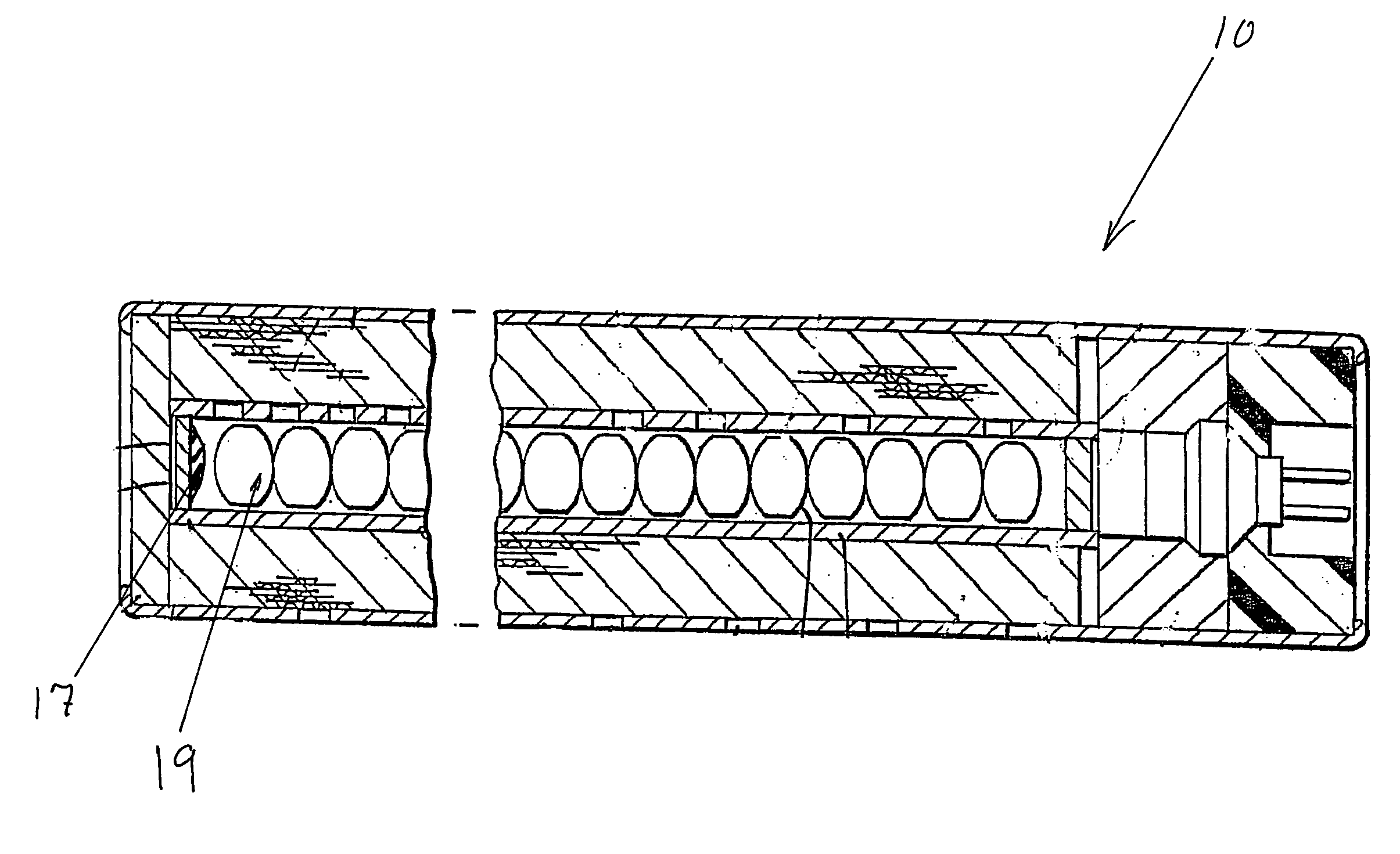
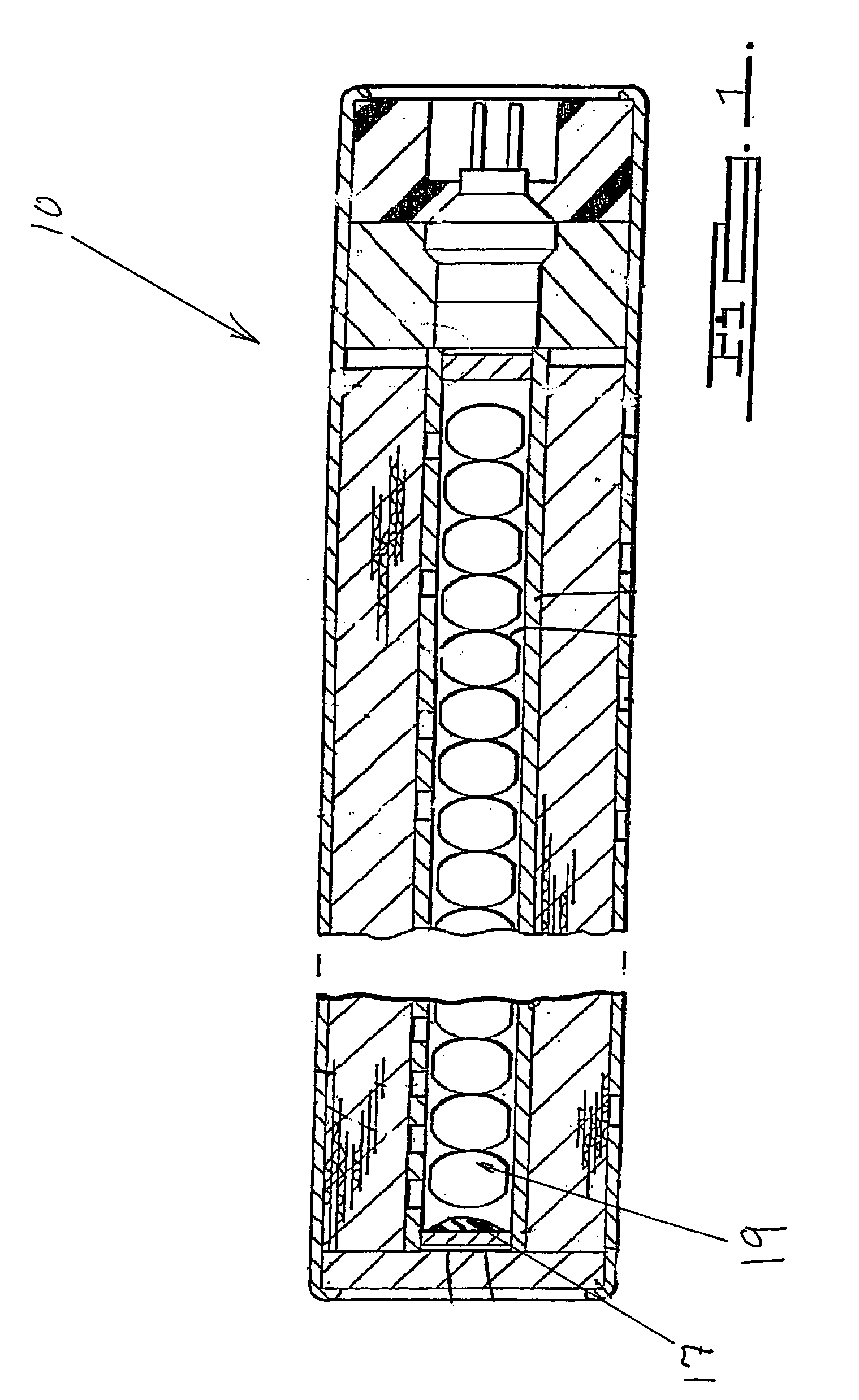
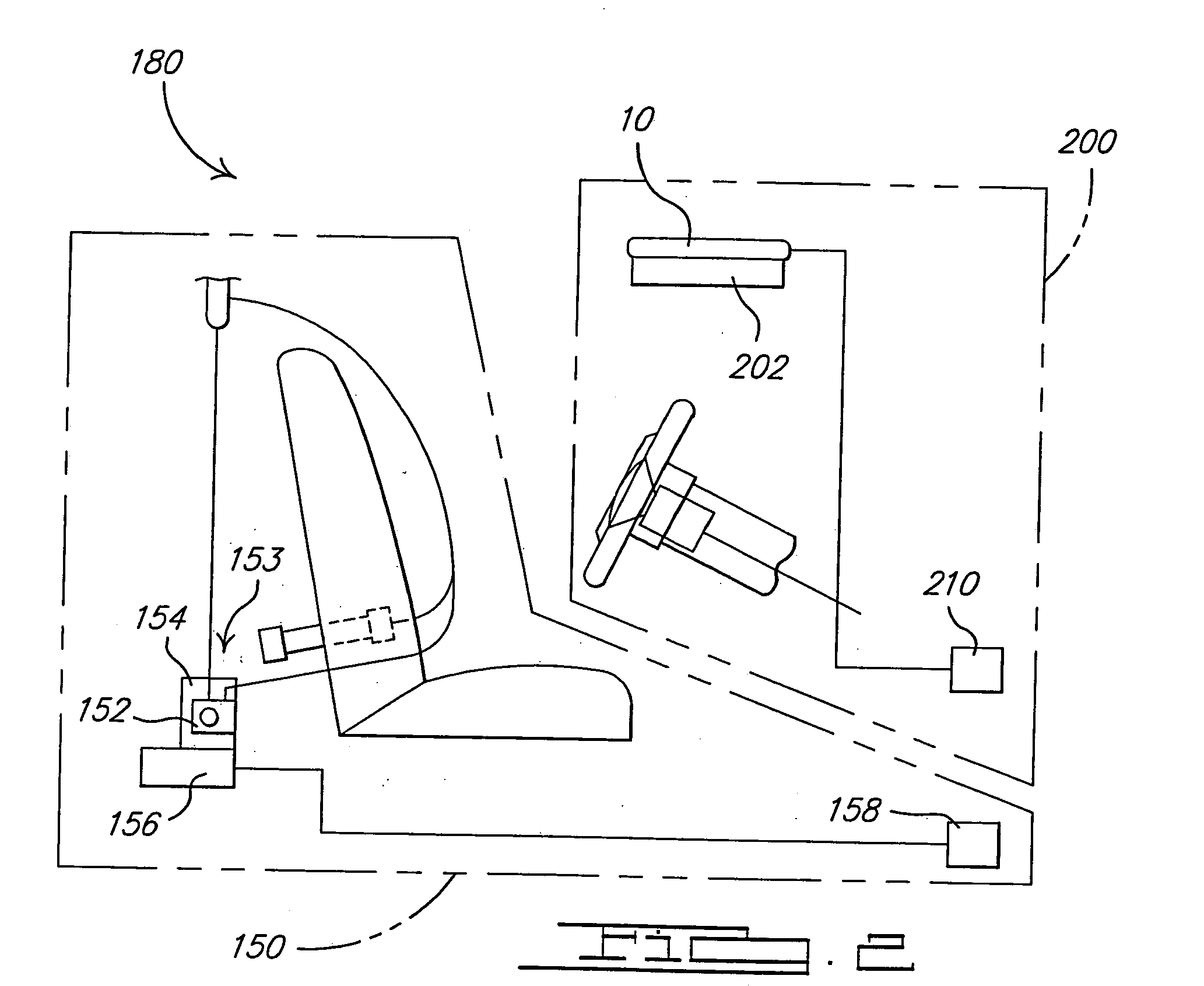
[0006] A pyrotechnic formulation including an auto-ignition fuel, an auto-ignition oxidizer, a booster fuel, a booster oxidizer, and an optional fuel / binder such as silicone that self-ignites at a specific design temperature or temperature range. The pyrotechnic also serves as a booster for pyrotechnic gas generators used as automotive gas generators or air bag inflators. Accordingly, the present compositions may function both as an auto-ignition pyrotechnic and as a booster charge pyrotechnic thereby eliminating the need for two separate compositions in the inflator.
[0007] Furthermore, the booster composition also propagates ignition of the main gas generation through flame and / or heat propagation. The sequence of events for the auto-ignition of an inflator includes the ignition of the auto-ignition material, which subsequently ignites the booster material, which in turn ignites the main gas generating pyrotechnic. This invention eliminates the need for individual auto-ignition and booster pyrotechnics, and replaces them with one single pyrotechnic component, greatly simplifying the inflator design, and improving inflator performance.
[0008] By integrating the auto-ignition and booster compounds into one composition, the single auto-ignition / booster grain can be molded or pressed to fit the desired inflator design. This component would be larger than a single auto-ignition tablet or grain, whereby a greater surface area facilitates increased heat conduction relative to primary gas generant and relative to the auto-ignition function in case of a fire. This single pyrotechnic also enhances the simplicity of the inflator design.

Problems solved by technology

An ongoing challenge is to continue simplification of gas generator manufacturing processes thereby resulting in lower overall costs.

Method used


Image

  • Auto-igniting pyrotechnic booster composition
  • Auto-igniting pyrotechnic booster composition
  • Auto-igniting pyrotechnic booster composition

Examples


Embodiment Construction

[0011] An auto-ignition component of the present invention includes a fuel, an oxidizer and an optional fuel / binder that self-ignites at a specific temperature. A fuel is preferably selected from sugars such as d-glucose and organic acids such as tartaric acid at about 15-45 weight percent of the composition. Exemplary organic acids include the various enantiomers of tartaric acid, malic acid, succinic acid, diglycolic acid, malonic acid, trans-glutaconic acid, adipic acid, mucic acid, 2,2-Bis(hydroxymethyl) propionic acid, citric acid, phenylmalonic acid, and quinic acid. Exemplary enantiomers of this group include D-tartaric acid, DL-tartaric acid, Meso-tartaric acid, D-glutamic acid, and D-quinic acid. The organic acid should preferably have a melting point ranging from about 125 to about 250° C. and pass a heat aging test at 107° C. for 400 hours. Typically, the material to be heat aged may be sealed in a glass vial and placed in an oven for 400 hours at 107° C. Or, the composit...


PUM

PropertyMeasurementUnit
weight percentaaaaaaaaaa
melting pointaaaaaaaaaa

Abstract

The present invention generally relates to auto-ignition / booster compositions for inflators of occupant restraint systems, for example. An exemplary auto-ignition composition in accordance with the present invention includes a metal chlorate, an auto-ignition fuel selected from the group including sugars and orgainic acids, and a nitrogen-containing secondary fuel.

Description

CROSS REFERENCE TO RELATED APPLICATIONS [0001] This application claims the benefit of U.S. Provisional Application Ser. No. 60 / 539,798 filed on Jan. 28, 2004.BACKGROUND OF THE INVENTION [0002] Auto-ignition materials in automotive air bag inflators allow the device to safely deploy in the event of a fire. By including an auto-ignition composition the likelihood of a safety hazard resulting from the bursting of an inflator is substantially reduced. [0003] On the other hand, pyrotechnic booster compositions raise the operating pressure of a pressure vessel or inflator prior to ignition of the main or primary gas generant. As a result, ready ignition of the primary gas generant is facilitated along with sustained combustion thereof. [0004] Accordingly, most inflators or gas generators for vehicle occupant protection systems, for example, typically include an auto-ignition composition juxtaposed next to a discrete booster composition. In the event of a fire, the auto-ignition compositio...

Claims


Application Information

Patent Timeline
Patent Type & Authority Applications(United States)
IPC IPC(8): C06B29/00C06D5/06
CPCC06D5/06C06B29/00
Inventor WILLIAMS, GRAYLON K.BURNS, SEAN P.KHANDHADIA, PARESH S.
Owner AUTOMOTIVE SYST LAB
Learn More