
Alloy tool steel

a tool steel and alloy technology, applied in the field of alloy tool steel, can solve the problems of difficult application to a large product, difficult application to the die for press forging used under severe conditions, and inability to apply to hot/warm plastic working dies under severe conditions, etc., to suppress the effect of lowering strength and improving the life of hot/warm plastic working dies

Inactive Publication Date: 2005-07-28
DAIDO STEEL CO LTD
View PDF0 Cites 17 Cited by
  • Summary
  • Abstract
  • Description
  • Claims
  • Application Information

AI Technical Summary

Benefits of technology

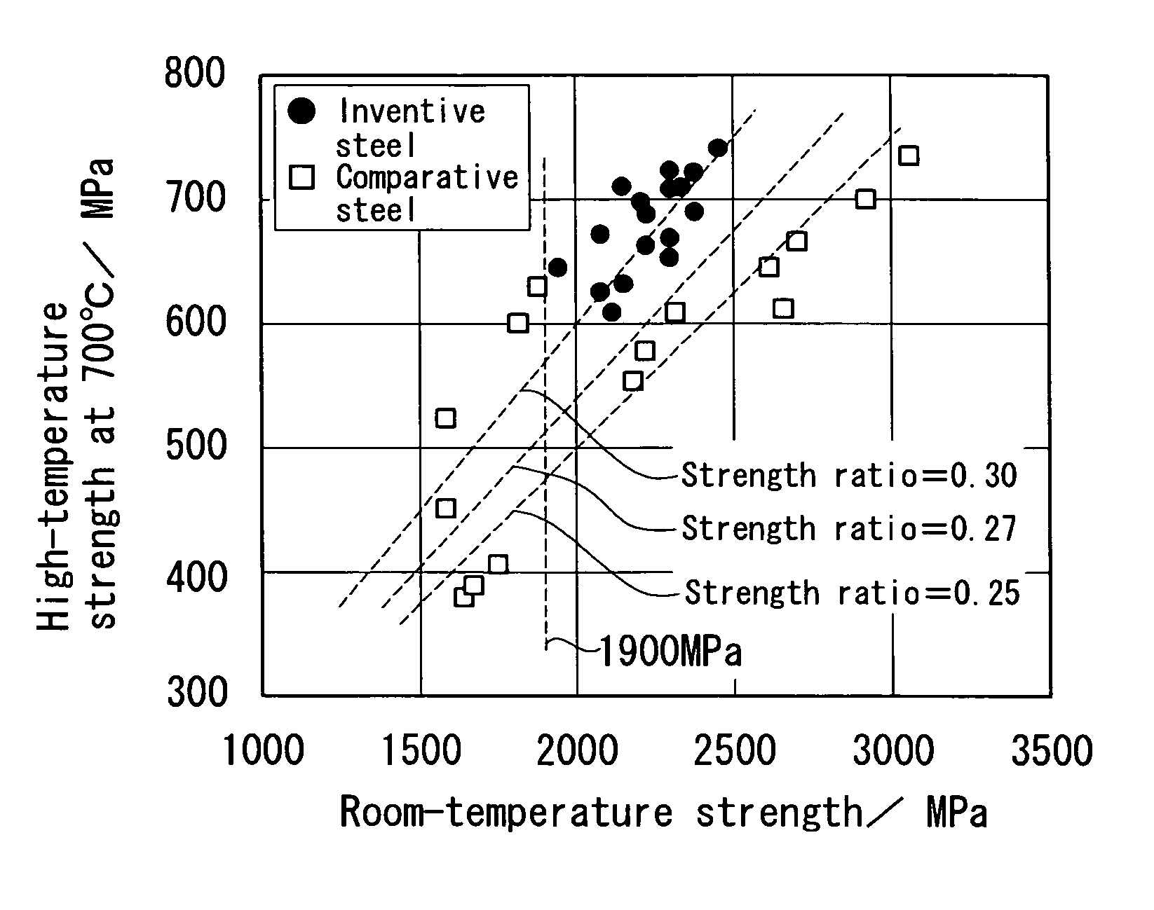
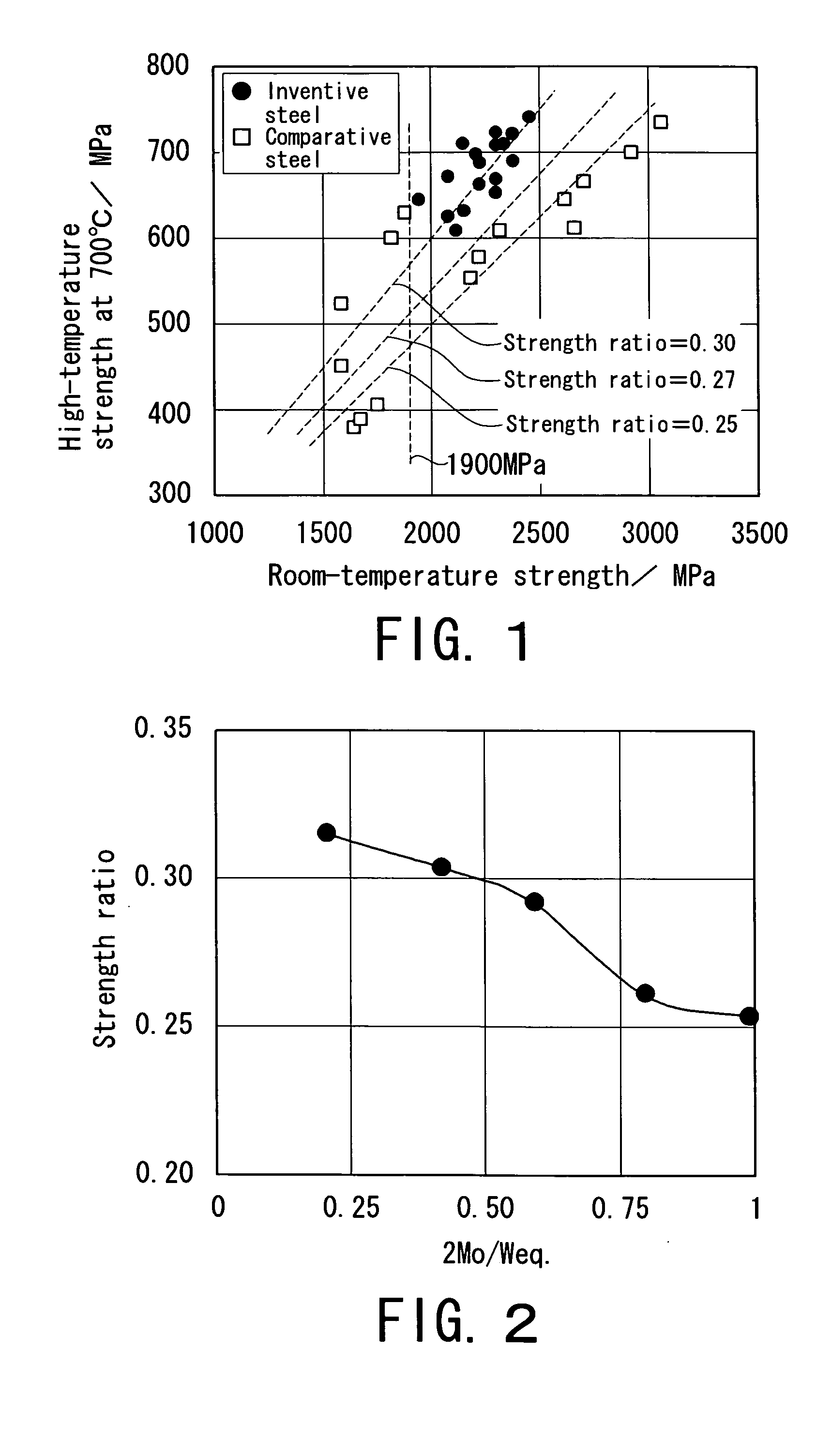
The invention provides an alloy tool steel that has high-temperature strength and maintains room-temperature strength, as well as improved lifetime of hot / warm plastic working dies. The alloy tool steel contains specific amounts of elements such as carbon, silicon, manganese, chromium, molybdenum, tungsten, vanadium, cobalt, aluminum, oxygen, nitrogen, and iron, among others. The ratio of molybdenum to tungsten is optimized to suppress lowering of strength at high temperatures while maintaining room-temperature strength. The alloy tool steel also has optimized ΔC, which results in high hardness and high toughness.

Problems solved by technology

However, as SKD61 has the maximum hardness on the order of 50 HRC and softening resistance is insufficient, it cannot be applied to hot / warm plastic working dies used under severe conditions.
However, even the W—Cr series hot die steel has the maximum hardness on the order of 55 HRC, and it is difficult to apply to dies for press forging used under severe conditions.
In addition, the forging die steel (for example, SKT4) has problems that (1) application to a large product is difficult due to its insufficient hardenability, and (2) the maximum hardness is on the order of 55 HRC, thus high strength is not secured.
However, as the conventional matrix high-speed tool steel is still insufficient in strength at 700° C., there is a problem that sufficient durability cannot be attained when it is applied in hot / warm plastic working during which an outermost layer reaches the order of 700° C.

Method used


Image

  • Alloy tool steel
  • Alloy tool steel

Examples


example

[0081] Table 1 shows elements in the alloy tool steels consistent with the present invention (inventive steels 1, 2-1 to 2-3, and 3 to 16). Further, Table 2 shows elements as comparative examples in the conventional matrix high-speed tool steels (1 to 6) and the conventional hot die steels (1, 2, SKD61, SKD7, SKD4, SKD5, SKD8, DH42, 2-4, and 2-5).

TABLE 1InventivesteelCSiMnPSCuNiCrMoWVCoNbAlTiB10.480.150.370.0090.0110.430.844.532.333.451.194.250.020.0082-10.540.310.480.0040.0080.240.144.310.514.021.482.030.0402-20.530.290.520.0060.0050.340.254.271.022.891.531.980.0032-30.550.330.530.0020.0070.150.374.231.482.111.461.940.01430.480.490.470.0040.0140.420.194.330.484.111.634.020.03640.520.440.490.0030.0120.130.044.330.484.251.854.020.120.0630.0150.580.880.310.0140.0090.560.433.590.895.341.221.020.02160.630.760.670.0090.0040.370.564.891.343.891.893.450.110.01170.520.480.990.0040.0070.210.664.661.893.331.016.220.050.00380.640.490.450.0180.0140.860.454.132.754.111.892.570.0070.00390.570.1...


PUM

PropertyMeasurementUnit
wt %aaaaaaaaaa
wt %aaaaaaaaaa
temperaturesaaaaaaaaaa

Abstract

To provide an alloy tool steel having high-temperature strength at an operating temperature of the order of 700° C., while maintaining room-temperature strength as high as that of a conventional matrix high-speed tool steel. The steel contains from 0.45 wt % to 0.65 wt % C, from 0.10 wt % to 1.00 wt % Si, from 0.20 wt % to 2.00 wt % Mn, not more than 0.020 wt % P, not more than 0.015 wt % S, not more than 1.00 wt % Cu, not more than 1.00 wt % Ni, from 3.50 wt % to 5.00 wt % Cr, from 0.00 wt % to 3.00 wt % Mo, from 0.00 wt % to 10.00 wt % W, from 1.00 wt % to 2.00 wt % V, from 0.00 wt % to 8.00 wt % Co, not more than 0.10 wt % Al, not more than 0.01 wt % O, not more than 0.02 wt % N, and the balance substantially constituted of Fe and unavoidable impurities, in which Weq is from 2.0 to 10.0, 2Mo / Weq is not more than 0.60, and ΔC is from −0.3 to 0.0.

Description

BACKGROUND OF THE TNVENTTON [0001] 1. Field of the Invention [0002] The present invention relates to an alloy tool steel, more specifically relates to an alloy tool steel which is applied to various tools including hot plastic working dies and warm plastic working dies. [0003] 2. Description of Related Art [0004] Conventionally, for hot / warm plastic working dies used under severe conditions (i.e., at high bearing pressures and high temperatures), W—Cr series hot die steels such as JIS-SKD8, which places importance on softening resistance, and forging die steels such as JIS-SKT4 are applied. [0005] In addition, in some fields of hot / warm working, a matrix high-speed tool steel is also used since high strength can be secured both at room temperatures and high temperatures. For example, Japanese Patent Application Unexamined Publications Nos. Hei2-8347 and Hei2-11736 disclose a hot working tool steel containing from 0.98 wt % to 1.61 wt % W and from 1.98 wt % to 2.55 wt % Mo in additio...

Claims


Application Information

Patent Timeline
Patent Type & Authority Applications(United States)
IPC IPC(8): C22C38/00C21D1/06C21D1/10C21D1/18C21D1/667C21D9/32C22C38/18C22C38/24C22C38/44C22C38/58C22C38/60
CPCC21D1/06C21D1/10C21D1/18C21D1/667C21D9/32C22C38/52C22C38/02C22C38/04C22C38/44C22C38/46C21D2261/00Y02P10/25
Inventor OZAKI, KOZO
Owner DAIDO STEEL CO LTD
Learn More