
Capacitive moisture sensor

a moisture sensor and capacitive technology, applied in the direction of resistance/reactance/impedence, instruments, measurement devices, etc., can solve the problems of inability to use in such a way, approaches that completely ignore the degrading effect of diode temperature, and cannot be exactly the same, etc., to achieve the effect of superior characteristics regarding reading stability

Active Publication Date: 2005-07-21
DELMHORST INSTR
View PDF10 Cites 9 Cited by
  • Summary
  • Abstract
  • Description
  • Claims
  • Application Information

AI Technical Summary

Benefits of technology

[0010] It is an object of the present invention to provide new and useful features which may be utilized individually or in combination, for the design and fabrication of a capacitance balanced moisture sensing apparatus which exhibits superior characteristics regarding reading stability, and particularly but not exclusively, regarding performance under conditions of differing temperatures.
[0011] Accordingly, another object of the invention is to provide a moisture sensing apparatus which comprises an oscillator with an output for supplying an AC signal and an operational amplifier with rectifier means for supplying a rectified signal that is proportional to a moisture content of material that is in contact with a contact plane of the contact sensor, the contact sensor comprising means defining an support substrate, a conductive sensor pad on the support substrate, a conductive driven ring on the support substrate, extending around the pad and spaced from the pad to define a first closed loop around the pad and a conductive ground plate on the support substrate, extending around the ring and defining a second closed loop around the ring, the pad, the ring and the plate all lying in the contact plane for the sensor, which contact plane is adapted to be in contact with a surface for measuring moisture content at the surface, as a function of capacitance across the loops, the pad, the ring, the plate, and the loops having no angular corners so as to minimize electrostatic field fringing effects.

Problems solved by technology

In virtually all instances, another diode or PN junction of a bipolar transistor is used for compensation, but due to circuit design constraints, it cannot be employed in such a way that the current versus time profile is exactly the same as the measurement rectification diode.
While the subject profile in each of the diodes or other PN junction devices can be quite similar, the profiles cannot be exactly the same, or no way will exist for extraction of a DC signal from the receiving electrode of the sensor.
Indeed, some design approaches totally ignore the degrading effects of diode temperature.

Method used


Image

  • Capacitive moisture sensor
  • Capacitive moisture sensor
  • Capacitive moisture sensor

Examples


Embodiment Construction

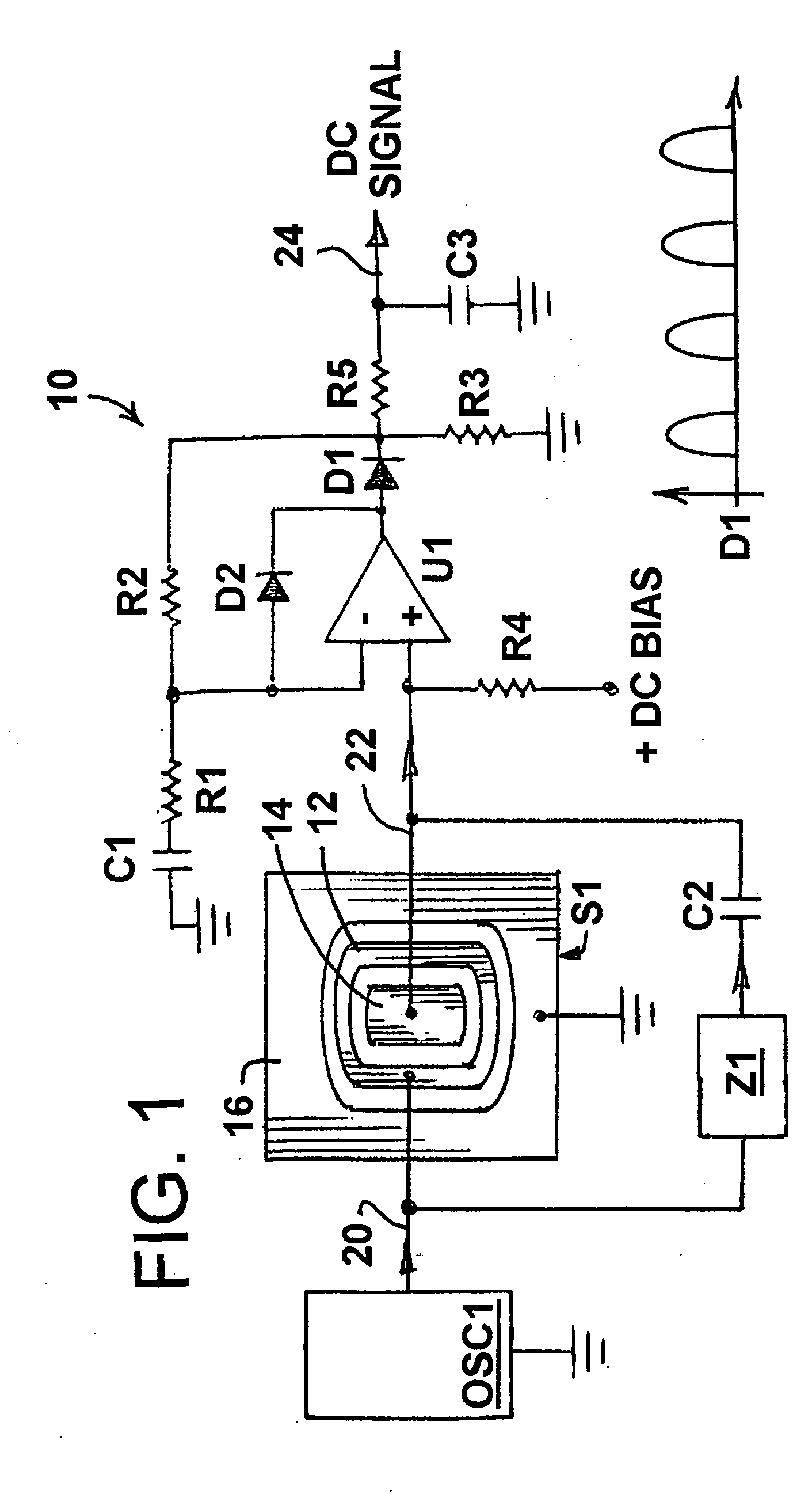
[0020] Referring now to the drawings, in which like reference numerals are used to refer to the same or similar elements, FIG. 1 illustrates a moisture sensing apparatus comprising an oscillator OSC1 having an output 20 for supplying an AC signal to the driven ring 12 of a contact sensor S1. The sensor S1 also has a sensor pad 14 spaced inwardly of the ring 12 by a first closed loop, and a common ground plane or plate 16, spaced around the ring 12 by a second closed loop.

[0021] The circuitry of the apparatus includes an operational amplifier U1 having one (non-inverting) input connected to the pad 14, and another (inverting) input. The amplifier U1 also has an output connected to a first diode D1 with an output of D1 supplying a rectified signal that is proportional to a moisture content of material that is in contact with the sensor S1.

[0022] Operational amplifier U1 is not provided with a negative power supply. Instead, ground is used. Therefore, the operational amplifier output...


PUM


Abstract

A moisture sensing apparatus includes an oscillator for supplying an AC signal to a driven ring of a sensor having a pad inside the ring, and a ground plate around the ring. An amplifier forms part of a temperature-compensated, precision rectifier, and is connected to the pad. A first diode connected to the output of the amplifier in a feedback loop of the amplifier, where the amplifier nullifies temperature variation effects upon the diode, and supplies a rectified signal which is a function of moisture content of material in contact with the sensor. A second diodes is connected between the amplifier output and other input of the amplifier. The sensor has a rounded configuration to avoid electrostatic field fringing effects, and a passive impedance with both resistive and capacitive members is connected in parallel with the sensor to provide a functional baseline for the rectified signal.

Description

FIELD AND BACKGROUND OF THE INVENTION [0001] The present invention relates generally to the field of moisture detectors, and, in particular, to a novel mechanism and method of signal processing for sensing of moisture in building construction materials, including wood, concrete, gypsum, roofing felt, various flooring and other materials. [0002] Although the approach illustrated is intended for use in moisture sensing by surface contact with a measurement sample, this is the preferred embodiment for the invention, with variations possible in sensor shape and configuration, and electronic circuitry described herein, known to those skilled in the art to be considered as integral to the spirit and scope of this disclosure. [0003] It is an object of this disclosure to illustrate novelty of the design approach and reading stability offered by the same. [0004] Many approaches to capacitive moisture measurement have been utilized over a substantial number of years. [0005] Virtually all rely...

Claims


Application Information

Patent Timeline
IPC IPC(8): G01N27/22G01R27/26
CPCG01N27/226G01N27/223
Inventor KATZ, BERNARD ROY
Owner DELMHORST INSTR
Learn More