Exposure method and apparatus

Inactive Publication Date: 2005-07-14
CANON KK
View PDF6 Cites 317 Cited by
  • Summary
  • Abstract
  • Description
  • Claims
  • Application Information

AI Technical Summary

Benefits of technology

[0007] Accordingly, it is an exemplary object of the present invention to provide an exposure method and apparatus, which maintains the high transmittance and high imaging performance using a NA of 0.85 or greater.

Problems solved by technology

This limit increases the design difficulty and requires a reduction of the transmission loss due to absorptions in the coating, contaminated substrate, and scattering in the coating layer, which has conventionally been negligible.
Although the phase change between the P-polarized light and the S-polarized light is negligible in a range below the Brewster angle, their transmission phase changes become large once the angle exceeds the Brewster angle and the influence to the aberration of the projection optical system cannot be negligible.
Therefore, the antireflection coating having a limited usable coating material for the F2, ArF and KrF lasers disadvantageously deteriorates both the transmittance and the imaging performance of the projection optical system once the NA of 0.85 or 58° of the light exceeds the Brewster angle.
While the immersion exposure apparatus disclosed in Japanese Patent Application, Publication No. 10-303114 uses the plane-parallel plate for the final optical element in the projection optical system and facilitates the replacement, an immersion structure of the plane-parallel plate at only the wafer side poses a problem of the total reflection at the interface between the plane-parallel plate and the air layer at the side of the projection optical system when the NA of the projection optical system exceeds 1.0.

Method used


Image

  • Exposure method and apparatus
  • Exposure method and apparatus
  • Exposure method and apparatus

Examples


Embodiment Construction

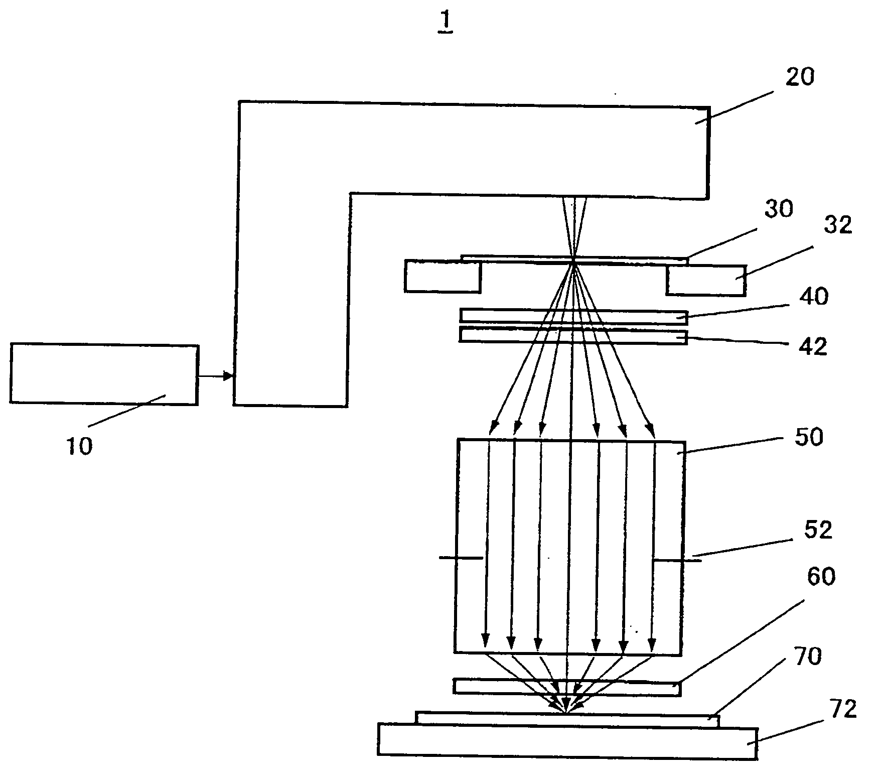
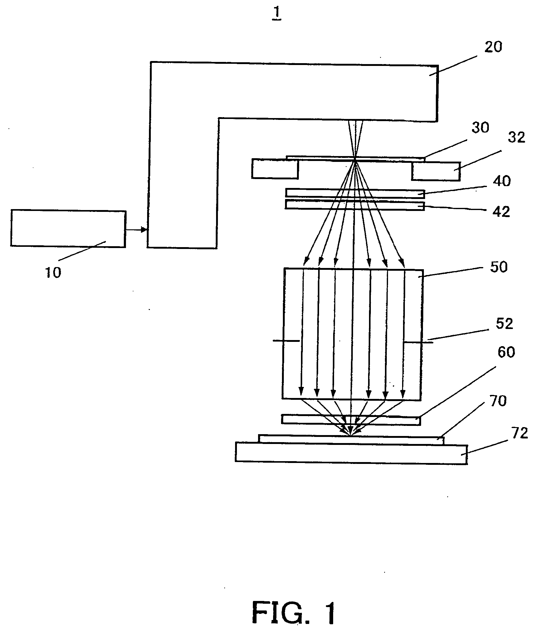
[0020] Referring now to FIGS. 1 and 2, a description will be given of an exposure apparatus 1 according to one embodiment according to the present invention. Here, FIG. 1 is a schematic block diagram of a projection exposure apparatus (scanner) 1. In FIG. 1, 10 denotes a light source, such as an excimer laser, another continuously oscillating laser, and a Hg lamp. 20 denotes an illumination optical system. 30 denotes a reticle (or a mask) placed on a reticle stage 32. 50 denotes a projection optical system that transfers a circuit pattern on the reticle 30 onto a resist applied wafer 70 placed on a wafer stage 72. The projection optical system 50 has an aperture stop 52 inside it, and projects the diffracted light within a predetermined aperture, from the circuit pattern on the reticle 30 onto the resist applied wafer 70 at a reduced size. A plane-parallel plate 60 is arranged between the projection optical system 50 and the wafer 70 so that the plane-parallel plate 60 can be replac...


PUM


Abstract

An exposure apparatus includes a projection optical system for projecting a pattern on a mask onto an object to be exposed, a final surface of the projection optical system and a surface of the object being immersed in a fluid, and a plane-parallel plate arranged between the projection optical system and the object, wherein the plane-parallel plate includes a first surface and a second surface that serves as a back surface of the first surface and opposes to the object, both the first and second surfaces being immersed in the fluid.

Description

BACKGROUND OF THE INVENTION [0001] The present invention relates generally to an exposure apparatus and method used to fabricate various devices including semiconductor chips such as ICs and LSIs, display devices such as liquid crystal panels, sensing devices such as magnetic heads, and image pickup devices such as CCDs, as well as fine patterns used for micromechanics, and more particularly to an immersion type exposure method and apparatus for immersing the final surface of the projection optical system and the surface of the object in the fluid and exposing the object through the fluid. [0002] The projection exposure apparatus employed to manufacture a semiconductor device, a liquid crystal display device, etc. is required to use an increased numerical aperture (“NA”) of a projection optical system and a shortened wavelength of an exposure light. A KrF stepper (with λ=about 248 nm) uses a NA of 0.65 in 2000. The projection exposure apparatus is being shifted from the stepper to a...

Claims


Application Information

Patent Timeline
IPC IPC(8): G03B27/52G03F7/20H01L21/027
CPCG03B27/52G03F7/70916G03F7/70341
Inventor KAWASHIMA, HARUNA
Owner CANON KK
Why Eureka
Try Eureka