
Method for anodizing aluminum materials

anodizing aluminum and aluminum materials technology, applied in the direction of anodisation, surface reaction electrolytic coating, electrolytic coating, etc., can solve the problems of not being able to keep using this method in the future, not being able to achieve all three characteristics at the same time, and having rather undesirable side effects. , serious drawbacks, etc., to achieve the effect of low porosity, high corrosion resistance and substantial porosity

Inactive Publication Date: 2005-07-14
KOCK ERICH +2
View PDF12 Cites 37 Cited by
  • Summary
  • Abstract
  • Description
  • Claims
  • Application Information

AI Technical Summary

Benefits of technology

[0025] The present method is suitable for all aluminum alloys, particularly also for high strength aluminum alloys particularly including corrosion sensitive aluminum alloys. Another advantage of the invention is seen in that the materials used for preparing the electrolytes are neither carcinogenic nor toxic. Still another advantage of the invention is seen in that the individual parameters of the electrolytes are easily adapted to the required functional and textural characteristics of the coatings to be produced. These parameters can be individually adapted in each of the individual anodizing steps.
[0026] The present method produces in a two step operation an oxide film particularly on aluminum alloys as they are used in the aircraft construction. The first anodizing step produces a first layer having preferably a thickness within the range of 1 to 2 μm. This first layer has a substantial porosity which is exceptionally well suited for adhesively bonding aluminum components to one another. The second anodizing step forms a low porosity layer having preferably a thickness within the range of 2 to 4 μm underneath the first layer. Presumably, the second layer formed in the second anodizing bath can grow below the first layer due to the substantial porosity of the first layer and probably due to a certain affinity between the aluminum material and the second electrolyte both. Further, it is possible to reverse the step sequence. More specifically, to perform the second step first and the first step last. In both possibilities the highly corrosion resistant layer will be formed between the aluminum surface and the adhesion enhancing outer anodized layer. The corrosion resistance of the second anodized layer can be further improved by a subsequent densifying step, for example by a rolling or pressing operation. As mentioned above, the present two step operation is equally suitable for all aluminum alloys used in the aircraft manufacture, particularly high strength aluminum alloys of the series 2XXX and 7XXX as well as for the weldable aluminum alloys of the series 6XXX. The preferred thicknesses of the layers produced according to the invention are within the range of 1.5 to 10 μm for the individual layers.

Problems solved by technology

So far, all three characteristics have not been achieved simultaneously without rather undesirable side effects.
However, there is a serious drawback because the electrolyte in the anodizing bath contains chromate which is a carcinogenic.
Therefore, even though the CAA method is currently widely used in aircraft construction, it will hardly be possible to keep using this method in the future.
However, a substantial drawback of an anodized layer produced by an electrolyte containing phosphoric acid, is seen in the rather limited corrosion protection characteristic.
However, phosphoric sulfuric acid anodization produces coatings that do not provide a sufficient corrosion protection.
However, these coatings are not suitable for adhesive bonding with other components.
However, these coatings are neither suitable for adhesive bonding nor as a base coating for lacquering.
However, the coatings are not suitable for adhesive bonding.
However, in view of its use of carcinogenic chromates chromic acid anodizing will not be suitable for continued use.

Method used


Image

  • Method for anodizing aluminum materials
  • Method for anodizing aluminum materials

Examples


Embodiment Construction

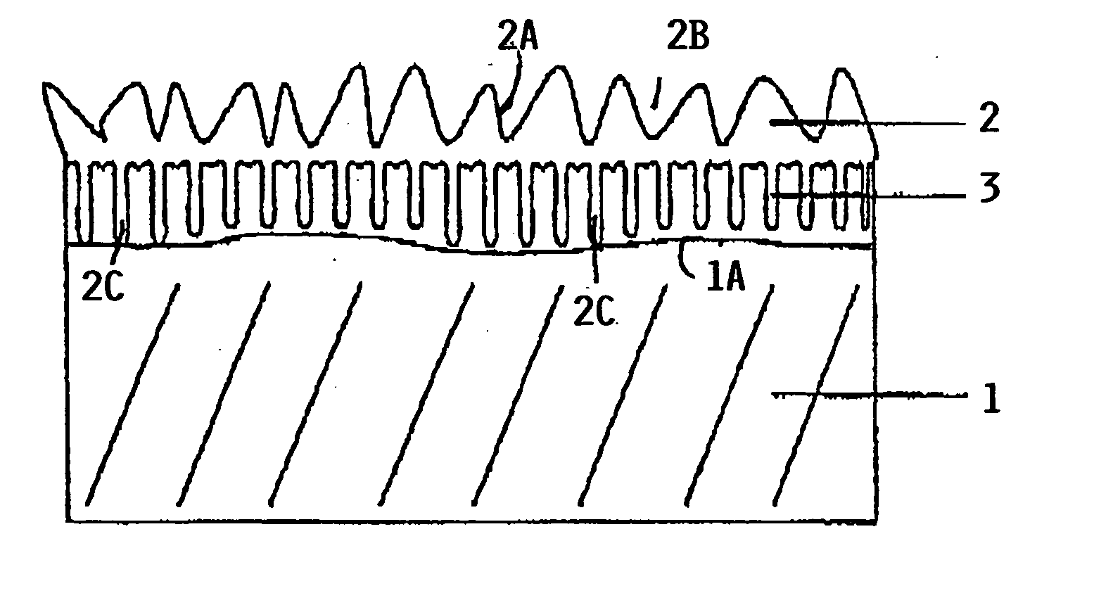
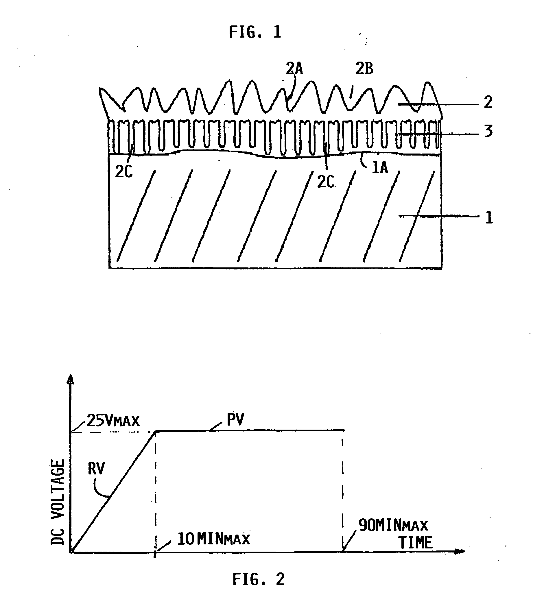
[0030]FIG. 1 shows an aluminum component 1 provided with a first anodized layer 2 and a second anodized layer 3. The layer thickness is exaggerated having regard to the fact that the thickness of the layers is within the range of a few microns, preferably in the range of 1 to 10 μm as mentioned above.

[0031] It will be noted that in FIG. 1 the anodized layer 2, which is produced first, appears as top layer having a very rugged surface 2A with deep pores 2B and roots 2C reaching into the second layer 3 shown to adhere to the surface 1A of the component 1. The second layer 3 is anodized after the first layer 2 has been anodized. Yet, the second layer 3 appears between the first layer 2 and the surface 1A. It is assumed that the second anodized layer 3 can grow through the deep pores 2B and then adhere to the surface 1A and to the first layer 2 due to affinities between the aluminum materials on the one hand and the two different electrolytes on the other hand. In this context it is po...


PUM

PropertyMeasurementUnit
DC voltageaaaaaaaaaa

Abstract

Structural components made of aluminum and aluminum alloys are anodized in two sequential steps in two different electrolytes. The first electrolyte is a mixed acid of two inorganic acids such as a phosphoric-sulfuric acid mixture. The second electrolyte is a further acid mixture of an organic acid and an inorganic acid to form a tartaric sulfuric acid mixture. The two sequential anodizing steps result in a surface texture that has three excellent surface characteristics simultaneously, namely: a corrosion resistance, a coating acceptance for lacquer coatings and an adhesive bonding with other aluminum material components.

Description

PRIORITY CLAIM [0001] This application is based on and claims the priority under 35 U.S.C. §119 of German Patent Application 103 61 888.0, filed on Dec. 23, 2003, the entire disclosure of which is incorporated herein by reference. FIELD OF THE INVENTION [0002] The invention relates to a method for anodizing aluminum materials, more specifically structural components made of aluminum and / or aluminum alloys. BACKGROUND INFORMATION [0003] It is known to anodize structural components made of aluminum materials including aluminum and aluminum alloys in two different sequential steps, whereby the respective different electrolytes comprise at least two components. The surface of the structural component is oxidized by applying a DC voltage to an electrolytic bath. At least one of the two electrolytes is a mixture of at least two inorganic acids forming an inorganic acid mixture. [0004] The coating of structural components of aluminum materials with an anodized layer is intended to change t...

Claims


Application Information

Patent Timeline
Patent Type & Authority Applications(United States)
IPC IPC(8): C23F11/00C25D11/04C25D11/06C25D11/08C25D11/10C25D11/12
CPCC25D11/04C25D11/024C25D11/12
Inventor KOCK, ERICHBENEKE, MARTINGERLACH, CARMEN
Owner KOCK ERICH
Learn More