Power supply device and printing apparatus having the same
a technology of power supply device and printing apparatus, which is applied in the direction of power conversion system, dc-dc conversion, instruments, etc., can solve the problems of overcurrent protection circuit operation error, overcurrent surge, and failure of main switching element qb>101/b>, so as to reduce the input rush current and reduce the time
- Summary
- Abstract
- Description
- Claims
- Application Information
AI Technical Summary
Benefits of technology
Problems solved by technology
Method used
Image
Examples
first embodiment
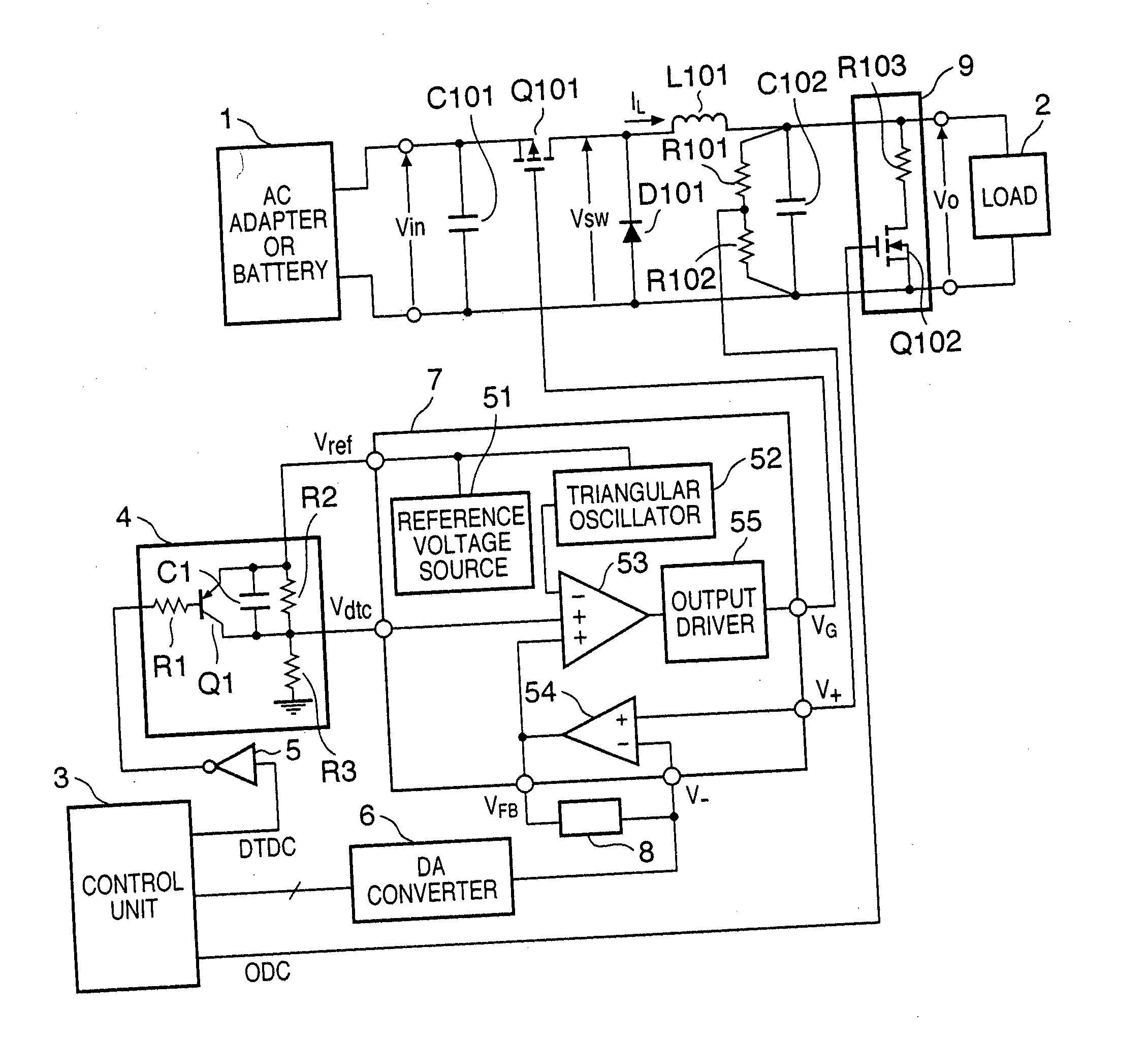
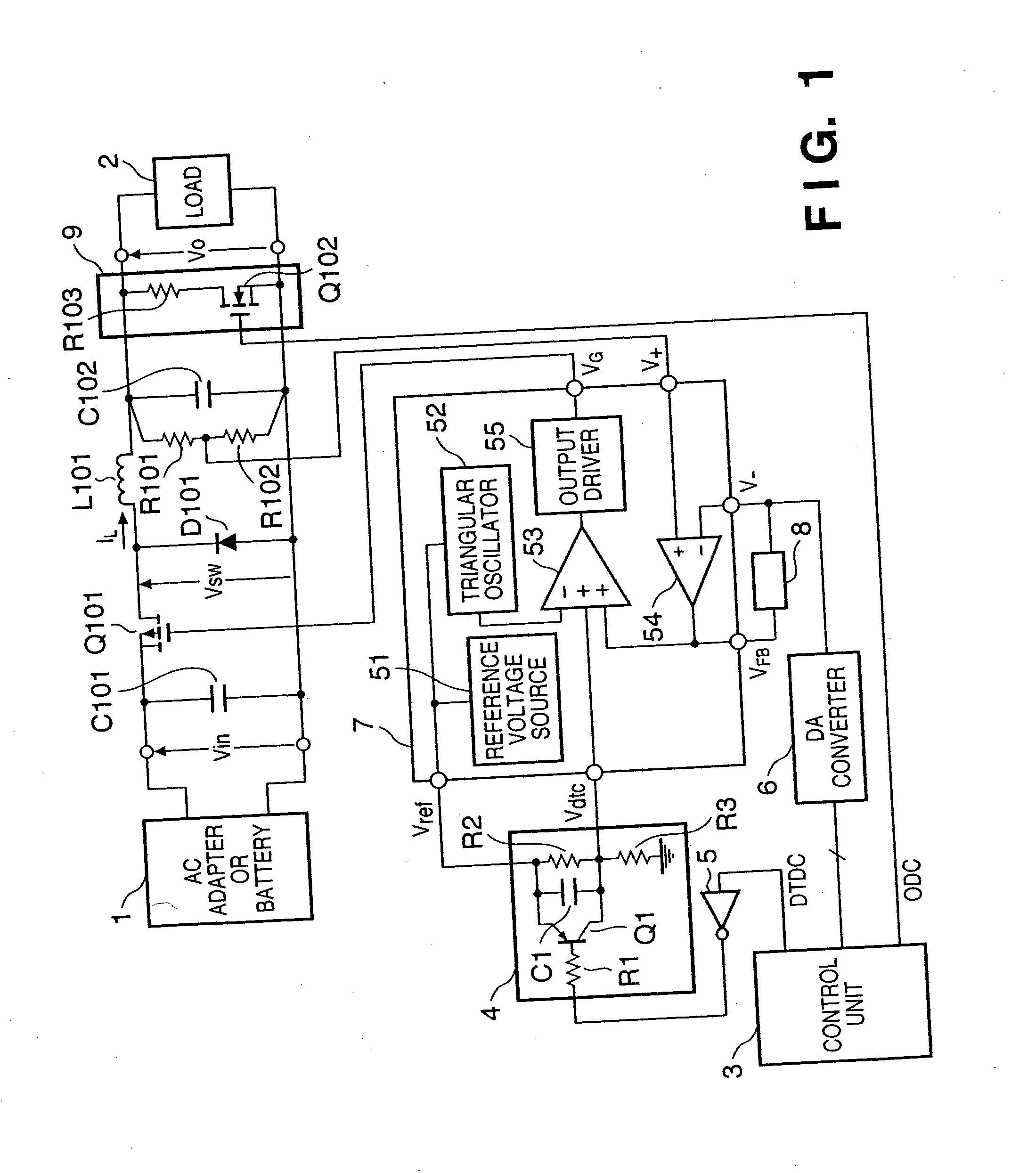
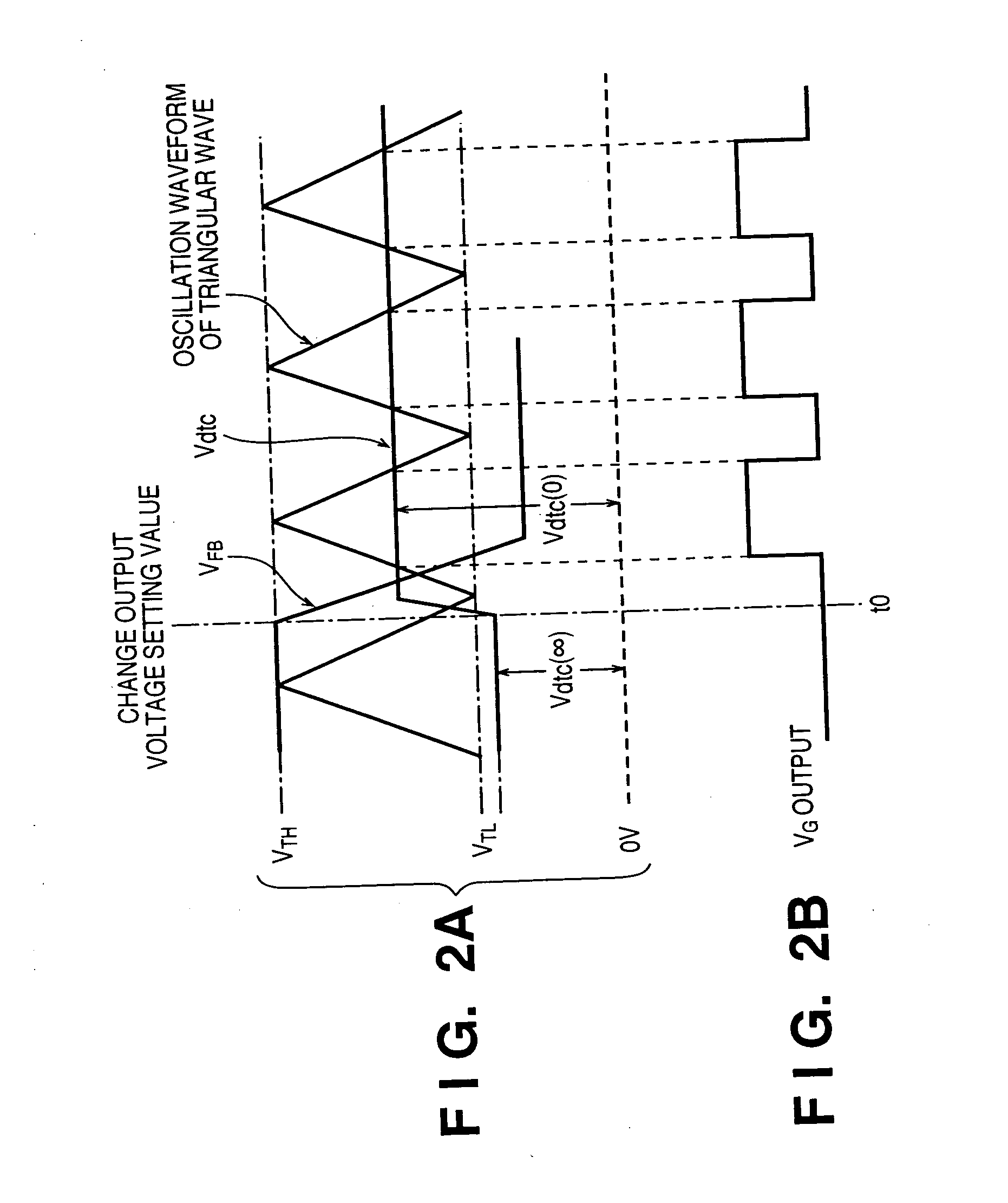
[0084] In this embodiment, when an output voltage setting value Vo(1) is low in the output voltage setting range, a voltage Vdtc(0) of a dead-time control circuit 4 is changed to a high voltage. With this operation, an increase in coil current IL can be limited by the upper limit value of the ON duty in PWM control, thereby reducing an input rush current. In this case, even if the ON duty value in PWM control is kept small, the ON duty in PWM control in the steady state is originally kept low because of a low output voltage. Even if the ON duty is strongly limited, the response time upon a change in voltage is not prolonged, and the time required to cause the output voltage to reach the setting voltage Vo(1) falls within a predetermined time.
[0085] When the output voltage before the change in voltage is high, the ON duty value in PWM control in the steady state is originally large. Unless the maximum ON duty (upper limit value or limit value of the ON duty value) in PWM control is ...
second embodiment
[0099] A DC / DC converter according to the second embodiment of the present invention will be described below. In the following description, portions which are the same as those of the first embodiment will not be described, and the characteristic portions of the second embodiment will be described below.
[0100] In the above first embodiment, the object of the present invention can be achieved. In the second embodiment, a rush current is further reduced, and a time required for causing an output voltage to reach a setting value is reduced. The basic circuit arrangement is the same as in FIG. 1.
[0101] In the present embodiment, it is a feature that in synchronism with a timing at which the setting signal of the output voltage output from a control unit 3 changes, a dead-time control voltage Vdtc(0) changes to obtain an ON duty which corresponds the voltage between the output voltage value before updating and the updated output voltage value.
[0102] In PWM control, the ON duty of a ma...
third embodiment
[0115] A DC / DC converter according to the third embodiment of the present invention will be described below. In the following description, portions which are the same as those of the first and second embodiments will not be described, and the characteristic portions of the third embodiment will be described below.
[0116] The DC / DC converter described in the first and second embodiments optimizes the operation in increasing an output voltage.
[0117] When reducing the output voltage, especially, when a load current is 0, it is difficult to set an output voltage to a target output voltage within a predetermined time only by adjusting the ON duty of a main switching element Q101. Hence, in the third embodiment, when a setting value Vo(1) of an output voltage from a control unit 3 is lower than a setting value Vo(0) of an output voltage before updating, a discharge circuit 9 for discharging a capacitor C102 connected between output terminals and a capacitor (not shown) arranged on a load...
PUM
 Abstract
Description
Claims
Application Information
 - R&D
- Intellectual Property
- Life Sciences
- Materials
- Tech Scout
- Unparalleled Data Quality
- Higher Quality Content
- 60% Fewer Hallucinations
Browse by: Latest US Patents, China's latest patents, Technical Efficacy Thesaurus, Application Domain, Technology Topic, Popular Technical Reports.
© 2025 PatSnap. All rights reserved.Legal|Privacy policy|Modern Slavery Act Transparency Statement|Sitemap|About US| Contact US: help@patsnap.com


