Respiratory monitoring during gas delivery

Inactive Publication Date: 2005-06-09
RIC INVESTMENTS LLC
View PDF82 Cites 151 Cited by
  • Summary
  • Abstract
  • Description
  • Claims
  • Application Information

AI Technical Summary

Benefits of technology

[0011] Accordingly, it is an object of the present invention to provide a simple system to monitor a subject's breathing while the subject is receiving a supplemental gas, such as supplemental oxygen or a gas mixture, that overcomes the shortcomings of conventional monitoring techniques. This object is achieved according to the present invention by providing a respiratory therapy and monitoring apparatus that includes a first conduit having a proximal end, a distal end, and a first lumen defined, therethrough from the proximal end to the distal end. A continuous flow of gas is delivered from a gas supply to an airway of a patient over a plurality of respiratory cycles. A first sensor is operatively coupled to the airway of the patient while the continuous flow of gas is passing through the conduit. The first sensor monitors a gas flow characteristic indicative of pressure or flow in the first conduit. In addition, a processor is provided that is adapted to determine at least one respiratory variable of such a patient based on the gas flow characteristic.

Problems solved by technology

The nasal cannula provides more freedom of movement for the patient than other methods of interfacing a flow of supplemental oxygen to a patient, but drawbacks of using the nasal cannula are well known and include unknown delivered FiO2, irritation of the nose, and potential dislodgment of the cannula from the patient's nostrils.
However, these conventional single lumen pressure sensing systems cannot be used when supplemental oxygen is to be provided to the patient because they are unable to provide a clear indication of the pressure variations produced by the patient.

Method used


Image

  • Respiratory monitoring during gas delivery
  • Respiratory monitoring during gas delivery
  • Respiratory monitoring during gas delivery

Examples


second embodiment

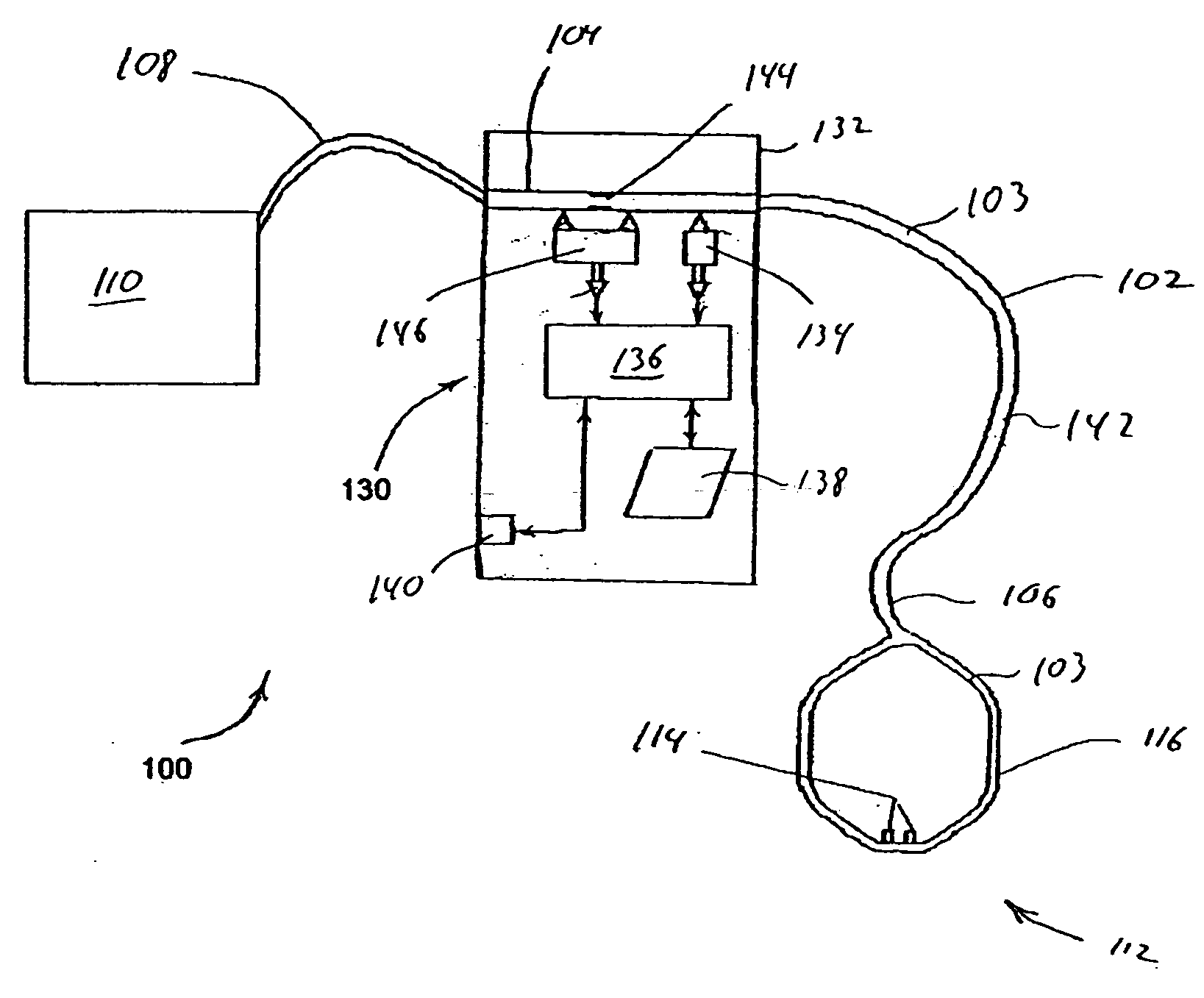
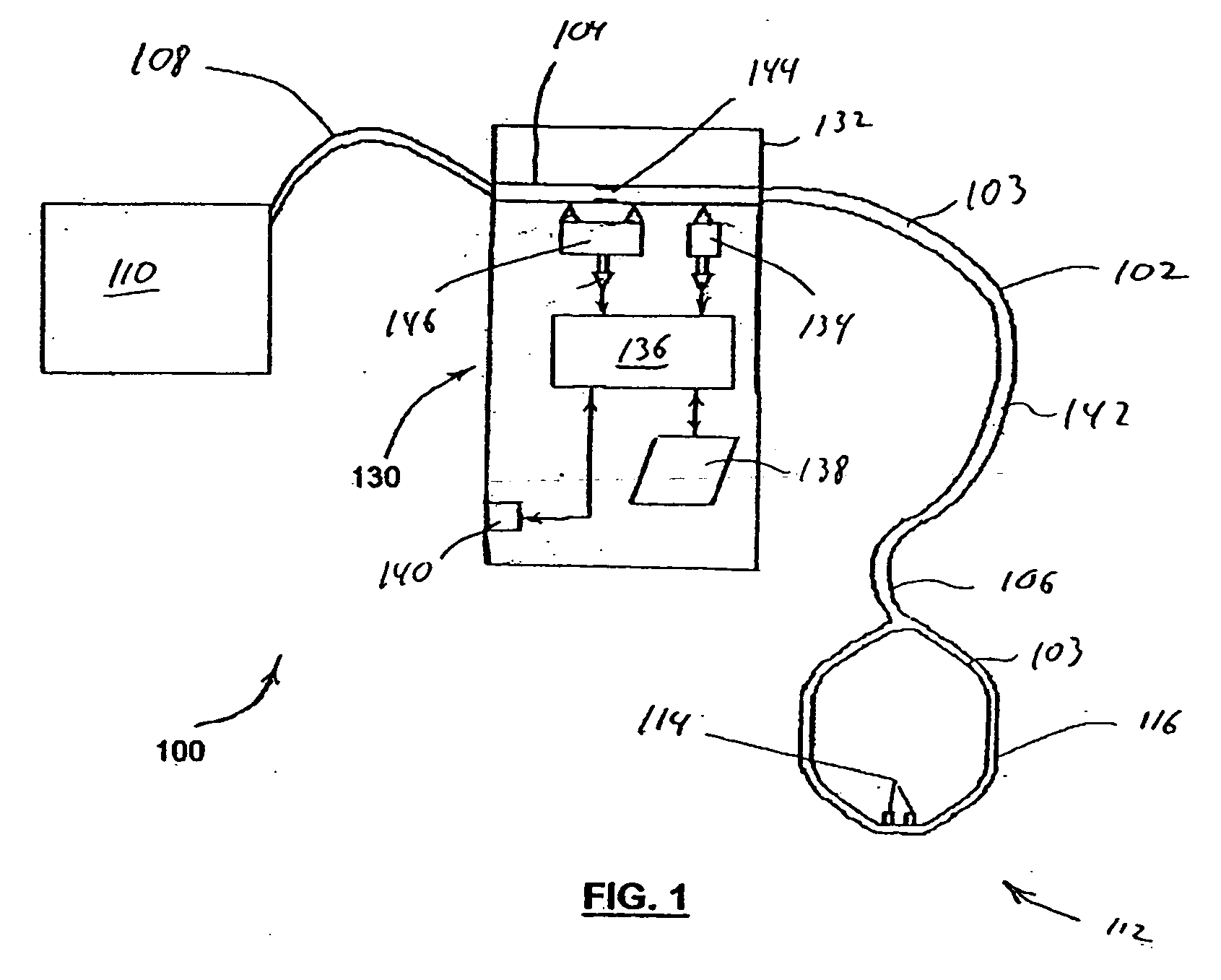
[0061] a respiratory monitoring system 100′ is shown in FIG. 7. In this embodiment, patient interface device 112′ is a face mask 148 coupled to distal end 106 of conduit 102. Additionally, a patient circuit 150 is connected to patient interface device 112′ (face mask 148) to carry a flow of gas from a ventilator or pressure support system 152 to the patient's airway in addition to the gas flow provided by conduit 102.

[0062] Facemask 148, when connected via patient circuit 150 allows the administration of continuous positive airway pressure (CPAP), bi-level positive airway pressure, auto-titrating pressure support, PAPP, PAV, ventilator, or any other conventional pressure support therapy. Patient circuit 150 may consist of a single lumen breathing tube with an exhalation port or valve provided on or near the mask, or two breathing tubes, with one tube used to apply inspiratory flow and the other tube to allow for expiratory flow from the patient. It should be readily apparent to one ...

third embodiment

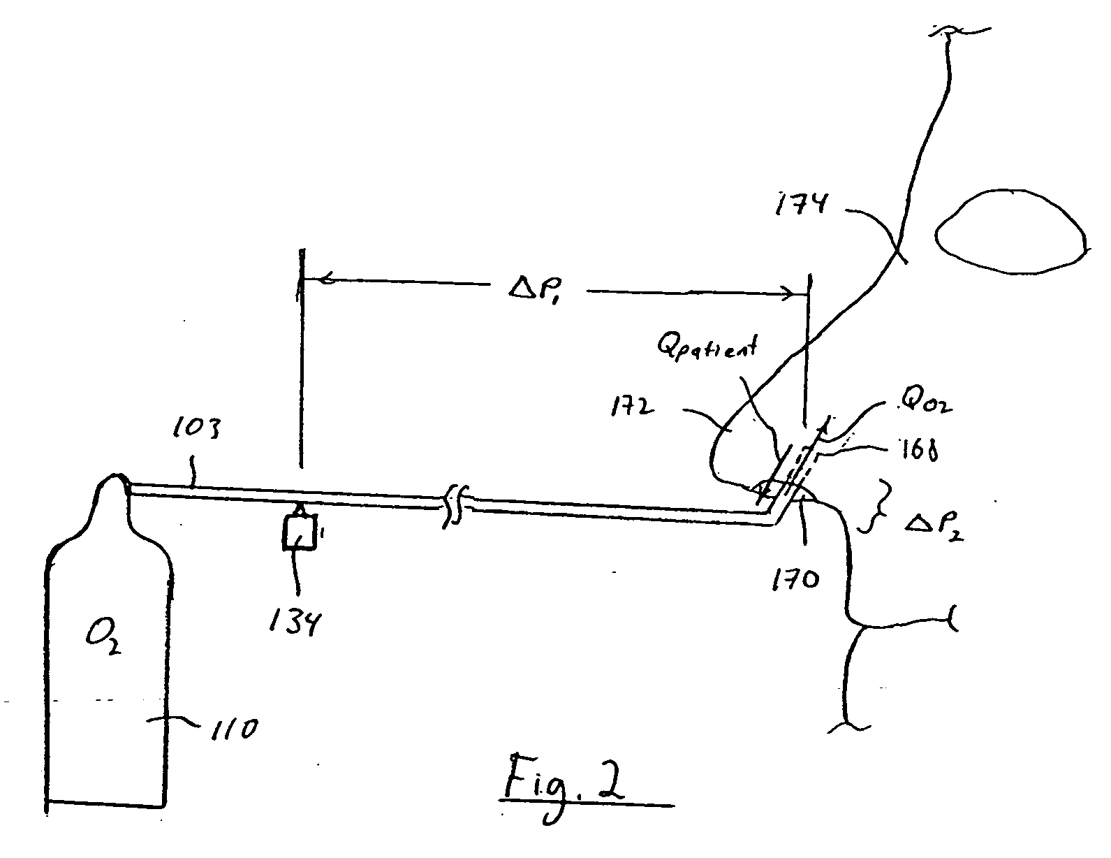
[0067] It can be appreciated that the flow or pressure of gas in second lumen 308, e.g., the output of pressure sensor 134′, will include a pressure drop ΔPO2 due to the flow of supplemental gas being delivered to the patient. For this reason, this third embodiment of the present invention, like the previous embodiments, contemplates removing or compensating for the pressure drop is generated due to the administration of the supplemental flow of gas ΔPO2. The techniques discussed above for accomplishing this function are, therefore, applicable to this embodiment.

[0068] It should also be noted that the proximal end of second lumen 308 can be connected to a flow sensor. That is, pressure sensor 134′ can be replaced with a flow sensor, and the proximal end of the second lumen can be open to atmosphere so that a flow is created in the second lumen due to the bias flow of gas. During patient respiration, gas flows into and out of prongs 311a and 311b cyclically. This flow of gas is illus...

sixth embodiment

[0077]FIG. 13 is a schematic diagram of a monitoring and therapy delivery system 400 according to the principles of the present invention. This embodiment is also similar to that of FIG. 1 except that an exhaust conduit 402 is provided from conduit 102 to ambient atmosphere. A flow sensor 404 is provided to measure the flow of gas passing through exhaust conduit 402. The flow of gas QTotal measured by flow sensor 404 will include (1) a flow of gas QO2 due to the continuous flow of oxygen being introduced into conduit 102, and (2) a flow of gas QBreathing due to patient breathing. Thus, flow sensor 404 provides a flow measurement comparable to the flow measurement made by flow sensor(s) in the previous embodiments.


PUM


Abstract

A method and apparatus for monitoring a patient's respiratory status during the delivery of gases, such as supplemental oxygen. In one embodiment, a conduit carries a continuous flow of gas to an airway of a patient over a plurality of respiratory cycles and a gas flow characteristic of the gas in the conduit is monitored using a pressure sensor, a flow sensor, or both. The gas flow characteristic is used to determine a respiratory variable for the patient.

Description

CROSS-REFERENCE TO RELATED APPLICATIONS [0001] This application claims priority under 35 U.S.C. § 119(e) from provisional U.S. patent application No. 60 / 536,132 filed Jan. 13, 2004, the contents of which are incorporated herein by reference. This application also claims priority under 35 U.S.C. § 120 as a Continuation-In-Part (CIP) from U.S. patent application Ser. No. 10 / 372,381 filed Feb. 21, 2003, which is a Continuation of Ser. No. 09 / 961,618 filed Sep. 24, 2001, now U.S. Pat. No. 6,544,192, which is a continuation-In-Part of Ser. No. 09 / 438,081 filed Nov. 10, 1999, now U.S. Pat. No. 6,342,040, which is a Continuation of Ser. No. 09 / 030,221 filed Feb. 25, 1998, now U.S. Pat. No. 6,017,315, the contents of all of these patents and application are hereby incorporated herein by reference.BACKGROUND OF THE INVENTION [0002] 1. Field of the Invention [0003] The present invention pertains to a method and apparatus for monitoring a patient's respiratory status during the continuous deli...

Claims


Application Information

Patent Timeline
IPC IPC(8): A61G11/00A61M16/00A61M16/04A61M16/06A61M16/08A61M16/10
CPCA61G11/00A61M16/1065A61M16/04A61M16/06A61M16/0666A61M16/0816A61M16/0875A61M16/1055A61M2016/0021A61M2016/0027A61M2016/0036A61M2016/0039A61M2202/0208A61M2205/3553A61M2205/3584A61M2205/3592A61M2205/502A61M2205/52A61M2205/60A61M2230/432A61M16/0627A61M16/0677A61M16/085A61M16/0051A61M16/0486A61M16/0858A61M16/101A61M16/024
Inventor STARR, ERIC W.HETE, BERNIE F.
Owner RIC INVESTMENTS LLC
Why Eureka
Try Eureka