
Film forming apparatus

a technology of film forming and film, which is applied in the direction of coating, chemical vapor deposition coating, metallic material coating process, etc., can solve the problems of limiting the capacity to increase the flow rate of the source gas, affecting the efficient depressurization of the source vessel, and the insufficient quantity of source gas produced by the source material, etc., to achieve the effect of improving the film forming rate and increasing the flow ra

Inactive Publication Date: 2005-06-09
TOKYO ELECTRON LTD
View PDF20 Cites 17 Cited by
  • Summary
  • Abstract
  • Description
  • Claims
  • Application Information

AI Technical Summary

Benefits of technology

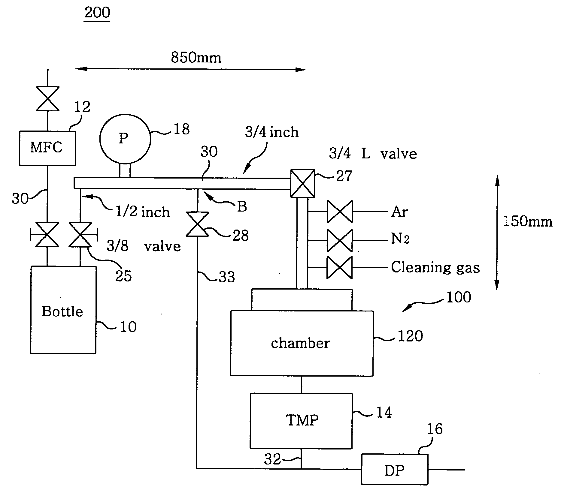
[0009] It is, therefore, a primary object of the present invention to provide a film forming apparatus capable of substantially improving the film forming rate by increasing the flow rate of a source gas supplied to a processing vessel of a semiconductor manufacturing device.
[0010] It is another object of the present invention to provide a film forming apparatus including a pre-flow line capable of substantially stabilizing the flow rate of a source gas before conducting a film forming process.
[0013] In the second aspect of the present invention, alternatively, the pre-flow channel may be made to join the gas exhaust channel at an upstream of the turbo molecular pump. In this case, since the vacuum pump system of the gas exhaust channel can be used while the pre-flow channel is activated, it is possible to reduce the difference between the pressure in the source vessel during the activation of the pre-flow channel and the pressure in the source vessel during the film forming process, without having to provide the second turbo molecular pump at the pre-flow channel.
[0014] In accordance with a third aspect of the present invention, there is provided a film forming apparatus including: a source vessel for accommodating a source material used to generate a source gas; a film forming chamber wherein a film forming process is performed on a semiconductor substrate; a source supply channel for supplying the source gas from the source vessel to the film forming chamber; a gas exhaust channel, having a vacuum pump system comprised of a turbo molecular pump and a dry pump, for exhausting the film forming chamber; and a pre-flow channel branching off from the source supply channel and joining to the gas exhaust channel, wherein the piping diameter of the pre-flow channel is enlarged to reduce a pressure difference between the pressure in the source vessel during the activation of the pre-flow line and the pressure in the source vessel during the film forming process.

Problems solved by technology

However, in case of a film forming process for the formation of high-k dielectric films or ferroelectric films, e.g., Ru films or W films, recently employed in semiconductor devices, the heating of the source material may not produce a source gas in a sufficient quantity due to its low vapor pressure.
However, as described above, even in case the source vessel 10′ and the like are depressurized by using the turbo molecular pump 14′ and the like, the capacity to increase the flow rate of the source gas is still restricted in case of using a low vapor pressure source material in addition to the small inner diameter, e.g., ¼ inch, of the piping generally used in the art.
Moreover, due to the small piping diameter, the pressure losses at the source supply line 30′ may hinder an efficient depressurization of the source vessel 10′ and, consequently, an efficient vaporization of the source material.
Thus, even in case the source gas is made to flow through the pre-flow line 33′ before the film forming process to stabilize the flow rate thereof, there still remains a problem that the flow rate thereof is not actually stabilized.

Method used


Image

  • Film forming apparatus
  • Film forming apparatus
  • Film forming apparatus

Examples


example 1

[EXAMPLE 1]

[0055] The results shown in FIG. 4 represent the differences between the pressure in the processing vessel 120 and that in the source vessel 10 obtained as a function of the piping diameter in accordance with the first preferred embodiment.

[0056] As shown in FIG. 4, in case a piping having the inner diameter of ¾ inch was employed for the source supply line 30 and the pressure in the processing vessel 120 was set to be 13.3 Pa (0.1 Torr), the pressure in the source vessel 10 was depressurized to 79.8 Pa (0.6 Torr).

[0057] Therefore, it can be seen that even in case a low vapor pressure source material, such as W(CO)6 with a vapor pressure of 3.99 Pa (0.03 Torr) at 25° C. and that of 33.25 Pa (0.25 Torr) at 45° C. is employed, the pressure in the processing vessel 120 can be sufficiently depressurized, so that a source gas of a sufficient flow rate can be obtained.

[0058] In the meantime, in case a piping having the inner diameter of ¼ inch was employed and the pressure i...

example 2

[EXAMPLE 2]

[0066] This Example was performed for the purpose of comparing the second embodiment of the present invention, described above, with the prior art illustrated in FIG. 5.

[0067] In this Example, pressure variances in the source vessel 10, which caused fluctuations in the flow rate of the source gas, were compared.

[0068] At first, using the conventional system shown in FIG. 5 as a comparative example, the mixed gas was made to flow through the pre-flow line 33′ before conducting the film forming process and then the pressure in the source vessel 10′ was measured by the pressure gauge 18′. Thereafter, by switching a flow path using the valve 26′, the mixed gas was provided into the source supply line 30′ which was connected to the processing vessel 120′, and then the pressure in the source vessel 10′ was measured by the pressure gauge 18′.

[0069] When the pre-flow line 33′ was activated, the pressure in the source vessel 10′ was 3990 Pa (30 Torr). However, when the source g...


PUM

PropertyMeasurementUnit
pressureaaaaaaaaaa
inner diameteraaaaaaaaaa
vapor pressureaaaaaaaaaa

Abstract

A film forming unit includes a source vessel for receiving a raw material from which source gas is produced, a processing vessel for applying a film forming process on a semiconductor substrate, a source supply line for supplying the source gas from the source vessel to the processing vessel, a gas exhaust line for exhausting gas from the processing vessel, having a vacuum pump system structured by a turbo molecular pump and a dry pump, and a pre-flow line branching off from the source supply line while bypassing the processing vessel and the turbo molecular pump, and joining to the gas exhaust line. Moreover, the source supply line includes piping having an inner diameter greater than 6.4 mm, and a turbo molecular pump is provided in the pre-flow line.

Description

[0001] This application is a Continuation Application of PCT International Application No. PCT / JP03 / 08800 filed on Jul. 10, 2003, which designated the United States. FIELD OF THE INVENTION [0002] The present invention relates to a semiconductor manufacturing apparatus; and, more particularly, to a semiconductor manufacturing apparatus capable of enhancing a film forming rate during a film forming process employing a low vapor pressure source material. BACKGROUND OF THE INVENTION [0003] With the recent increase in the size of semiconductor substrates, the semiconductor manufacturing apparatus tends to perform a single substrate processing, rather than a batch processing used to simultaneously treat a plurality of semiconductor substrates. In order to improve the processing efficiency or throughput of the apparatus which performs the single substrate processing, the processing time per substrate need be shortened. Accordingly, attempts have been made to increase the flow rate of a sou...

Claims


Application Information

Patent Timeline
Patent Type & Authority Applications(United States)
IPC IPC(8): C23C16/16C23C16/44
CPCC23C16/16C23C16/45561C23C16/4412
Inventor YAMASAKI, HIDEAKIKAWANO, YUMIKOYAMAMOTO, NORIHIKO
Owner TOKYO ELECTRON LTD
Learn More