
Fibrous marker formed of synthetic polymer strands

a synthetic polymer and fibroblast technology, applied in the field of remote detection and intracorporeal markers, can solve the problems of misdirected follow-up treatment to an undesired portion of the patient's tissue, inability to detect the disease, and inability to cure or otherwise change, so as to facilitate identification and ease the difficulty in manufacturing the marker

Inactive Publication Date: 2005-06-02
SENORX
View PDF98 Cites 131 Cited by
  • Summary
  • Abstract
  • Description
  • Claims
  • Application Information

AI Technical Summary

Benefits of technology

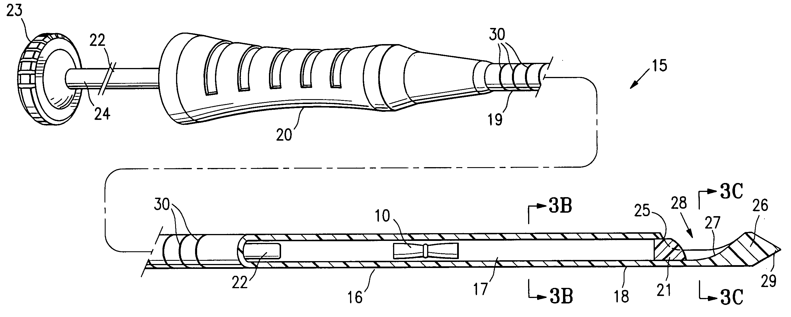
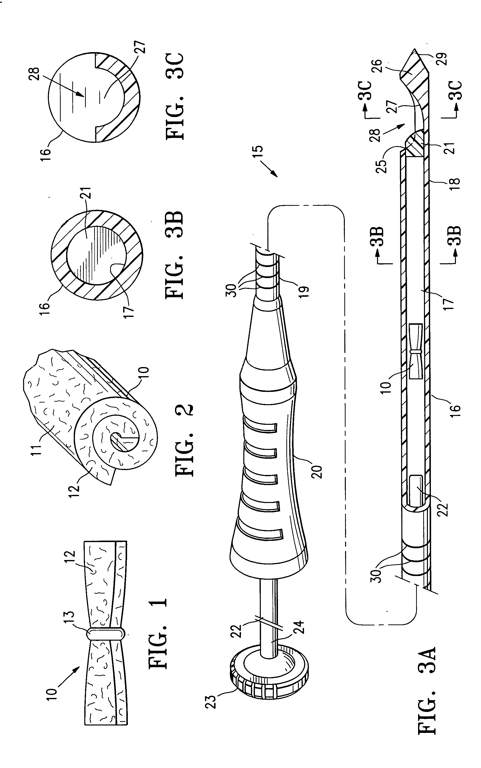
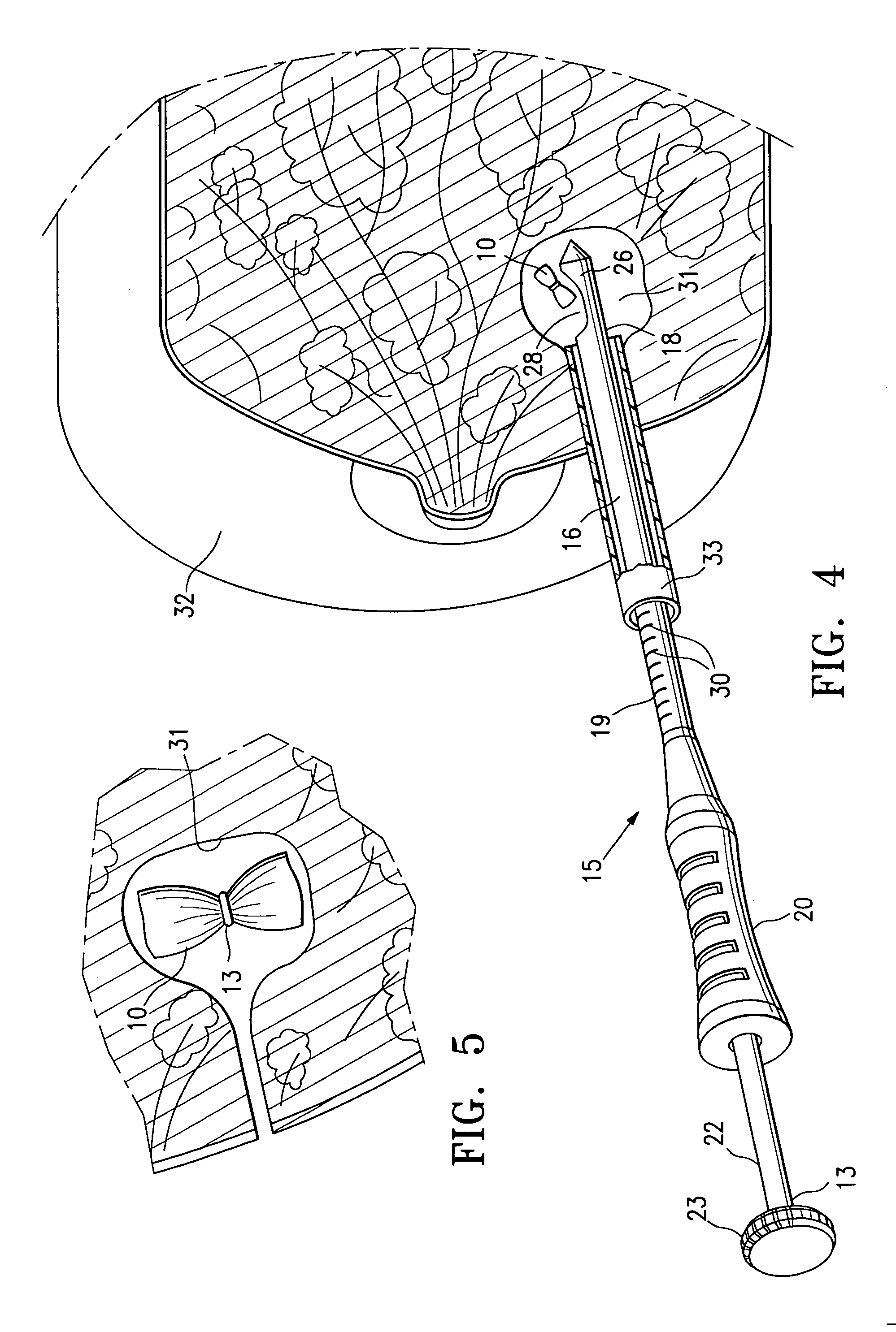
[0015] The fibrous marker embodying features of the invention can be readily delivered to the desired location by suitable delivery systems. The marker delivery system generally has an elongated cannula or syringe-like body with proximal and distal ports and an inner lumen extending between the ports. The fibrous marker is slidably disposed within the inner lumen of the delivery cannula and a plunger slidably disposed within the inner lumen of the delivery cannula proximal to the marker. The plunger is movable from an initial position proximal to the fibrous marker within the tube, to a delivery position close to the discharge opening in the distal end of the cannula to push the fibrous marker out of the discharge opening into the target tissue site.
[0021] The fibrous markers embodying features of the present invention provide several advantages. The synthetic polymeric strands are preferably hydrophobic which eases the difficulty in manufacturing the markers because they do not react with surrounding moisture. Moreover, the fibrous marker material is stabilized quickly in the intracavity clot which forms at the biopsy site and can be readily identified from surrounding tissue of the cavity by less skilled radiologists or surgeons.

Problems solved by technology

However, radiographically visible tissue features, originally observed in a mammogram, may be removed, altered or obscured by the biopsy procedure, and may heal or otherwise become altered following the biopsy.
This, in turn, can result in follow-up treatments being misdirected to an undesired portion of the patient's tissue.
Such a marker enables a follow-up procedure to be performed without the need for traditional radiographic mammography imaging which, as discussed above, can be subject to inaccuracies as a result of shifting of the location wire as well as being tedious and uncomfortable for the patient.

Method used


Image

  • Fibrous marker formed of synthetic polymer strands
  • Fibrous marker formed of synthetic polymer strands
  • Fibrous marker formed of synthetic polymer strands

Examples


Embodiment Construction

[0035]FIGS. 1 and 2 illustrate a fibrous marker 10 embodying features of the invention. The fibrous marker 10 is a rolled body 11 formed of fibers or strands 12 with a radiopaque non-magnetic ring or wireform 13 encircling at least part of the central portion of the rolled body. The fiber or strands 12 are formed of bioabsorbable synthetic polymeric material that is essentially hydrophobic and has an effective in-vivo life-span of at least three weeks, preferably at least four weeks. The fibrous marker body 11 is a rolled (or folded) and preferably compressed fibrous mat with binding material incorporated into the fibrous body to maintain the compressed condition. The rolled fibrous body 11 may be formed from a felt (as shown) or woven material. Preferably, the binding agent is a water soluble polymer such as polyethylene glycol which is incorporated into the fibrous body 11 and the body compressed to reduce the profile of the body and facilitate sliding the rolled body through a lu...


PUM


Abstract

The invention is directed to an intracorporeal fibrous marker formed of a fibrous pad or mat with strands of synthetic polymeric material such as polyglycolic acid and delivery devices and methods of using such devices. The fibrous pad or mat has a bulk density of at least 10, preferably about 30 to about 100 mg / cc and typically about 40 mg / cc. The fibrous marker has an effective in vivo lifespan of at least three weeks.

Description

RELATED APPLICATIONS [0001] This application is a continuation-in-part of application Ser. No. 10 / 444,770, filed on May 23, 2003 which is incorporated herein by reference in its entirety and from which priority is claimed.FIELD OF THE INVENTION [0002] The invention is generally directed to remotely detectable, intracorporeal markers and devices and methods for the delivery of such markers to a desired location within a patient's body. BACKGROUND OF THE INVENTION [0003] In diagnosing and treating certain medical conditions, it is often desirable to mark a suspicious body site for the subsequent taking of a biopsy specimen, for delivery of medicine, radiation, or other treatment, for the relocation of a site from which a biopsy specimen was taken, or at which some other procedure was performed. As is known, obtaining a tissue sample by biopsy and the subsequent examination are typically employed in the diagnosis of cancers and other malignant tumors, or to confirm that a suspected les...

Claims


Application Information

Patent Timeline
IPC IPC(8): A61B17/00A61B19/00
CPCA61B17/0057A61B19/54A61B2017/00831A61B2017/00889A61M37/0069A61B2017/00898A61B2019/5408A61B2019/5425A61B2019/5487A61B2017/00893A61B90/39A61B2090/3908A61B2090/3925A61B2090/3987
Inventor JONES, MICHAEL L.LUBOCK, PAULMALCHOW, LLOYD H.
Owner SENORX
Learn More