
Method for controlling laser beam machine and laser beam machine

a laser beam machine and laser beam technology, applied in the direction of optical radiation measurement, instruments, manufacturing tools, etc., can solve the problems of complex apparatus structure, almost impossible to monitor whether an object to be machined is irradiated with a laser beam, etc., to prevent molten scattering objects

Inactive Publication Date: 2005-06-02
FUJITSU LTD
View PDF6 Cites 22 Cited by
  • Summary
  • Abstract
  • Description
  • Claims
  • Application Information

AI Technical Summary

Benefits of technology

The present invention provides a method and apparatus for controlling a laser beam machine that can monitor the effective energy of a laser beam without affecting its properties. This allows for real-time monitoring of the laser beam's passage and the object it is irradiating, as well as detecting and notifying of maintenance issues. The apparatus includes an optical detection sensor along the laser beam transmission path, a collimator lens, and an arithmetic control section for receiving the sensor's output and performing a predetermined process to obtain the characteristic of the laser beam. The invention also includes a lens protection glass to prevent molten scattering objects from adhering to the machining convergent lens.

Problems solved by technology

In the conventional method, however, it is necessary to interpose optical components in an optical path (an optical transmission path), therefore, problems are brought about in that the structure of the apparatus becomes complex, the characteristics of a laser beam vary each time the laser beam is reflected by an optical component or the laser beam passes through an optical component, etc.
Generally, as described above, monitoring is performed only at the inside of a laser beam oscillator, in most cases, and it has been almost impossible to monitor whether an object to be machined is irradiated with a laser beam, or to monitor the change in the effective irradiation energy, with which the object to be machined is actually irradiated in the case where some optical component is damaged in an optical transmission path.

Method used


Image

  • Method for controlling laser beam machine and laser beam machine
  • Method for controlling laser beam machine and laser beam machine
  • Method for controlling laser beam machine and laser beam machine

Examples


Embodiment Construction

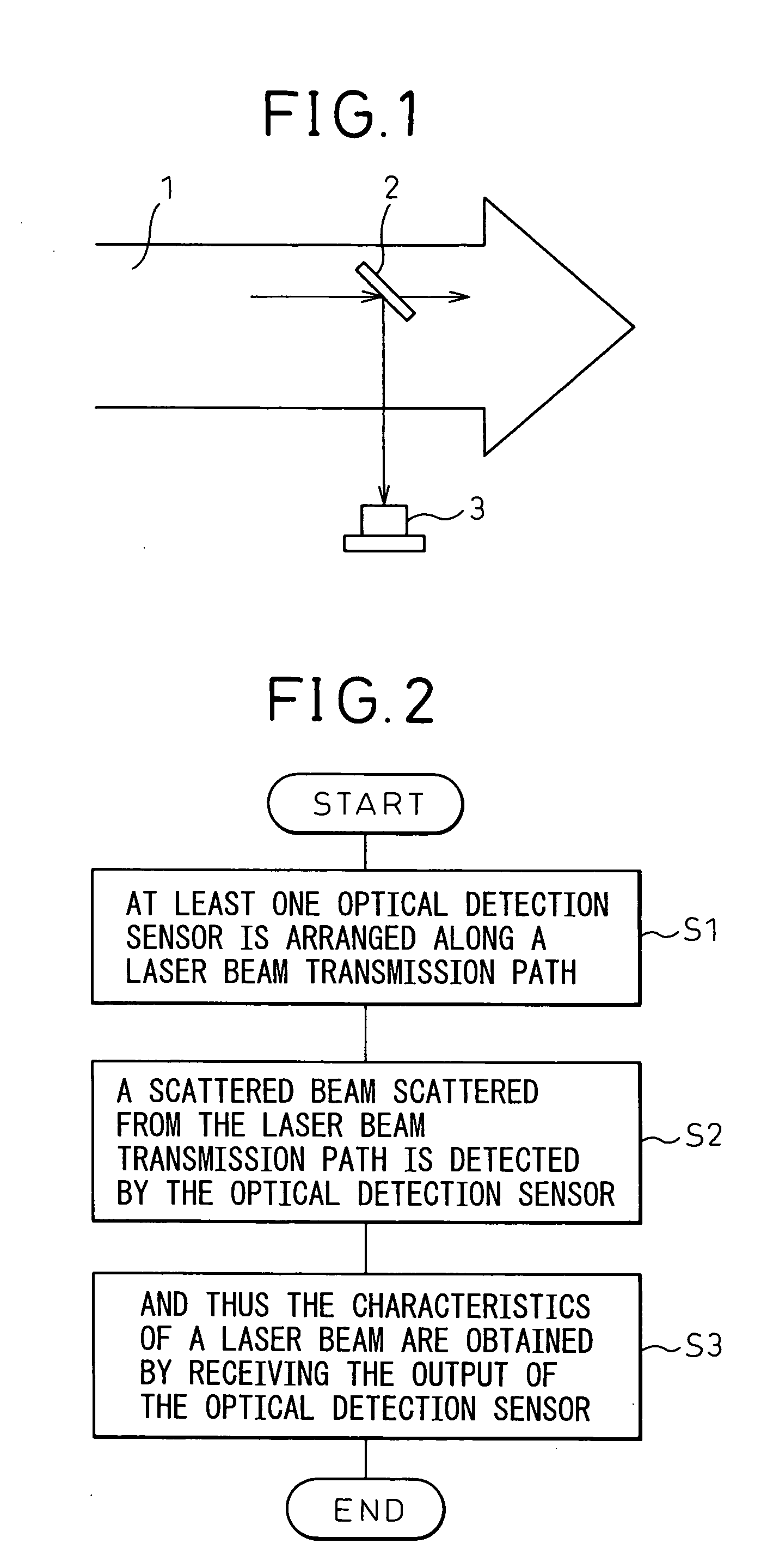
[0031]FIG. 2 is a flow chart showing the principles of the method according to the present invention. The present invention is characterized in that at least one optical detection sensor is arranged along a laser beam transmission path (S1), a scattered beam scattered from the laser beam transmission path is detected by the optical detection sensor (S2), and thus the characteristics of a laser beam are obtained (S3) by receiving the output of the optical detection sensor.

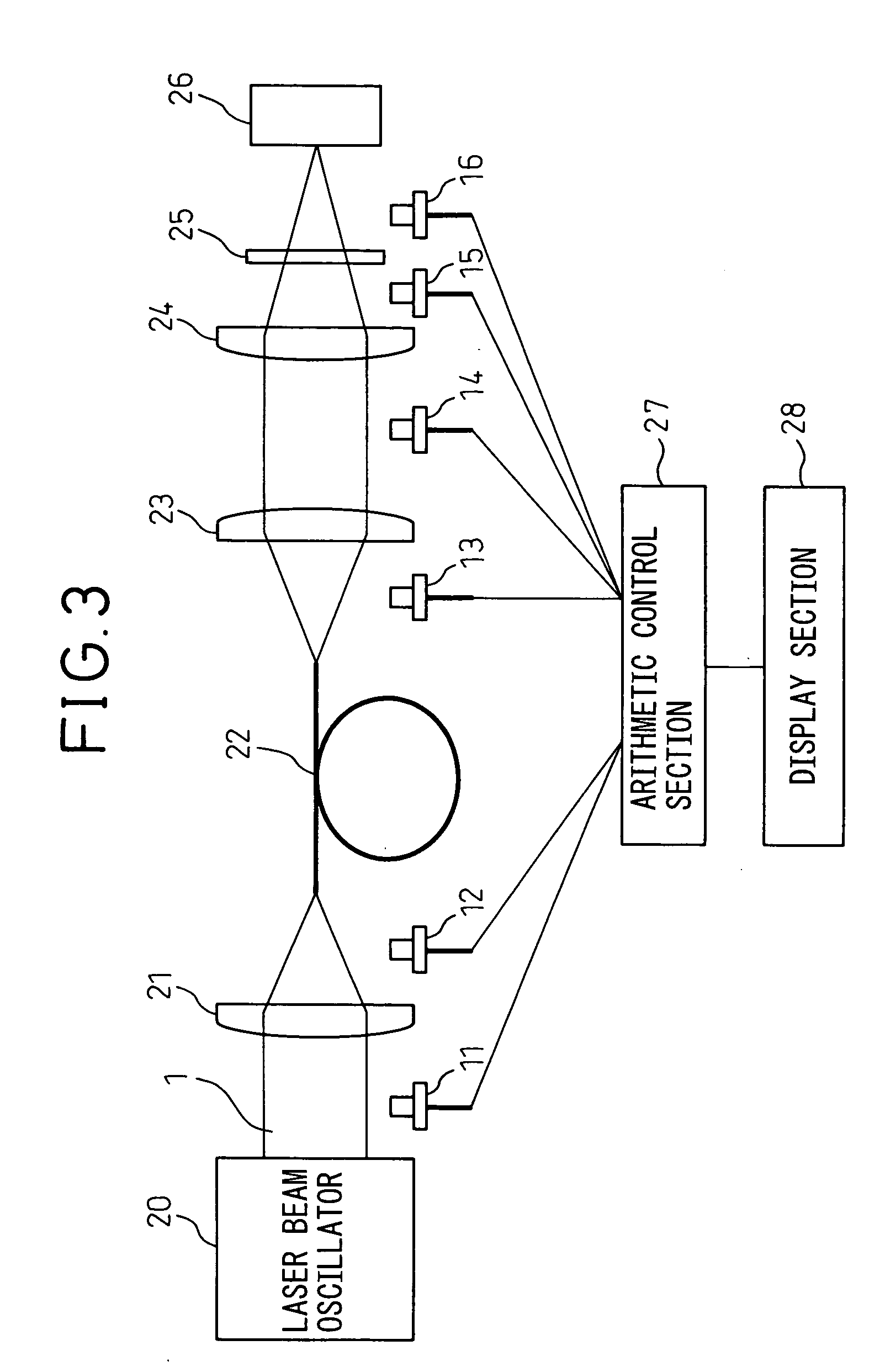
[0032]FIG. 3 is a diagram showing a configuration based on the principles of the present invention. In the figure, reference numeral 20 denotes a laser beam oscillator that produces laser beams, 1 denotes the laser beam produced by the laser beam oscillator 20, 21 denotes a condenser lens for guiding beams into an optical fiber, which receives the laser beams 1 and gathers and guides the beams into an optical fiber, 22 denotes an optical fiber as a laser beam transmission path that transmits a laser beam produced b...


PUM

PropertyMeasurementUnit
energyaaaaaaaaaa
strengthaaaaaaaaaa
flexibilityaaaaaaaaaa

Abstract

A laser beam machine and a laser beam machine capable of monitoring the effective energy of a laser beam oscillator, with which an object to be machined is irradiated, and the state of oscillation without affecting the properties of a laser beam, is disclosed. A laser beam machine comprises: a laser beam oscillator; a laser beam transmission path; a collimator lens; a machining condenser lens; at least one optical detection sensor provided along the laser beam transmission path; and an arithmetic control section for receiving the output of the optical detection sensor and performing a predetermined process to obtain the characteristic of a laser beam.

Description

BACKGROUND OF THE INVENTION [0001] The present invention relates to a method for controlling a laser beam machine and to a laser beam machine. [0002] Laser beam machining is widely used in various fields of such as drilling, cutting, welding and thermal treatment of various materials, because non-contact, high-speed, and high-quality machining is possible. Another advantage is that the above-mentioned various kinds of machining can be performed by a single laser beam oscillator only by changing the laser beam oscillation conditions. [0003] However, such enormous flexibility brings about the possibility of a danger that the quality of machining may suffer from changes in the laser beam oscillation conditions and the irradiation conditions for an object to be machined, for some reason. Therefore, maintaining the quality of machining is a problem. [0004] Conventional techniques relating to a laser beam machine include, for example, a technique disclosed in Japanese Unexamined Patent Pu...

Claims


Application Information

Patent Timeline
Patent Type & Authority Applications(United States)
IPC IPC(8): B23K26/00G01J1/42H01S3/00
CPCG01J1/4257B23K26/426B23K26/705
Inventor MATSUSHITA, NAOHISAIIDA, SUSUMU
Owner FUJITSU LTD
Learn More