
Method and system for an immersion boiling heat sink

Inactive Publication Date: 2015-01-22
GENERAL ELECTRIC CO
View PDF6 Cites 16 Cited by
  • Summary
  • Abstract
  • Description
  • Claims
  • Application Information

AI Technical Summary

Benefits of technology

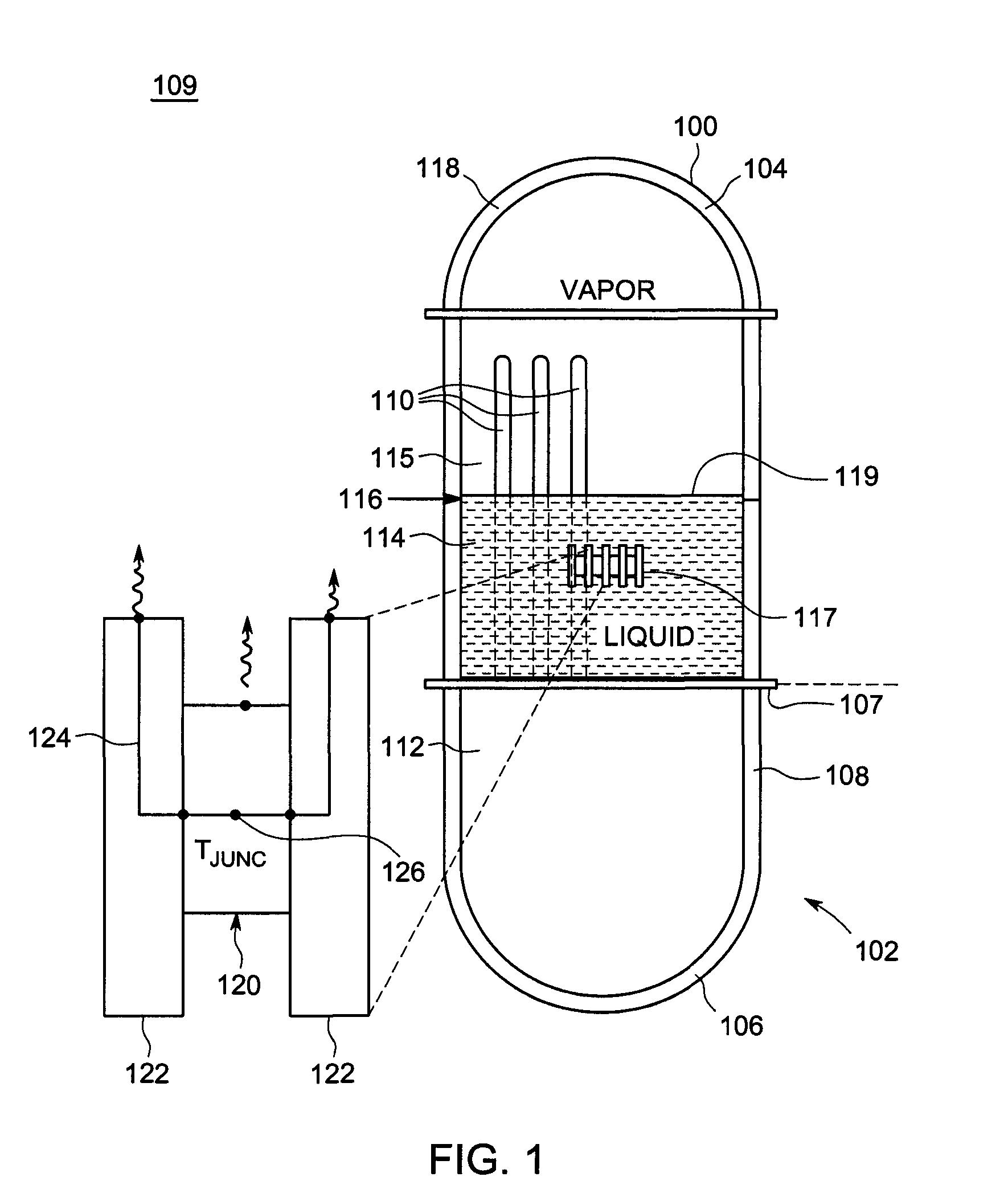
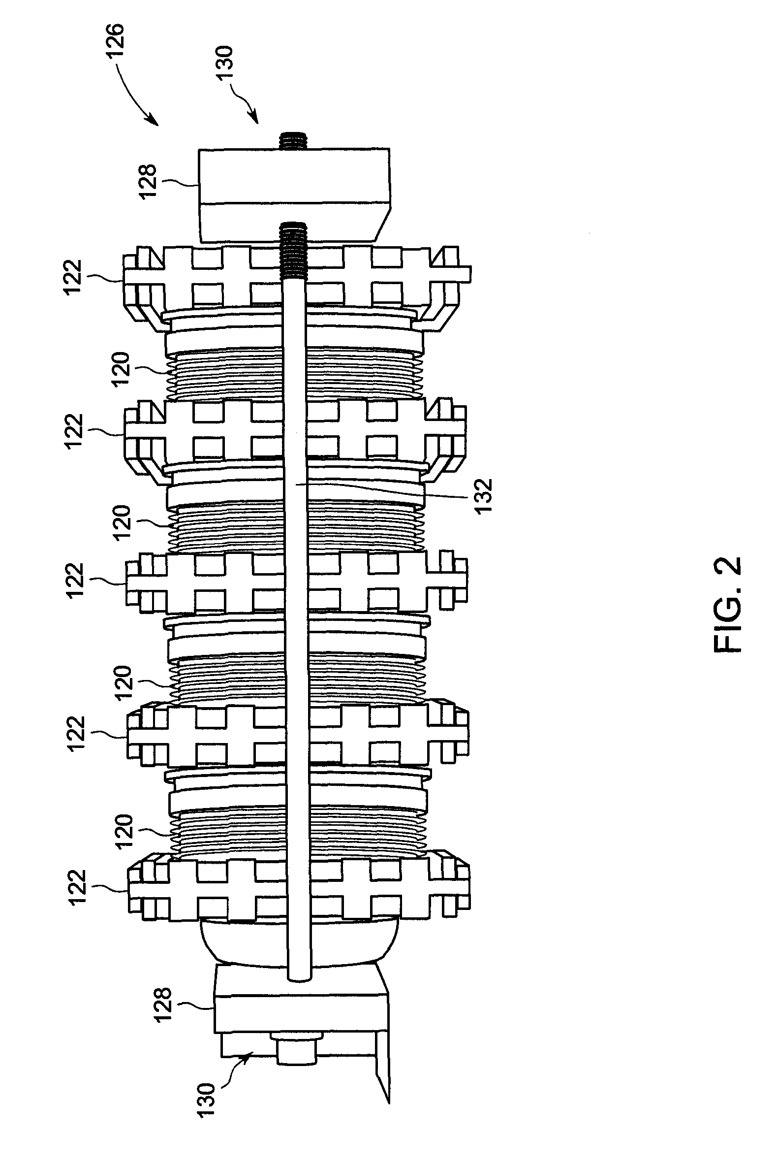
The patent describes an electronic component cooling system that uses a heat sink device with fins that transfer heat to a dielectric fluid. This fluid boils and partially vaporizes in the system, taking heat away from the component. The vapor then condenses back on the inner surface of the system. This design can be used in a subsea power electronic device, where the heat sink device is clamped between the power electronic devices and the dielectric fluid is used to transfer heat away from the system. The patent also describes a method for cooling the heat-generating component by positioning the heat sink device in direct contact with the component and immersing them in a cooling fluid. The technical effects of the patent are improved cooling efficiency and the ability to handle high levels of heat generation in a subsea environment.

Problems solved by technology

Pool type cooling of power electronics has been attempted, however due to the heat sink design used, the heat transfer performance has been problematic.

Method used


Image

  • Method and system for an immersion boiling heat sink
  • Method and system for an immersion boiling heat sink
  • Method and system for an immersion boiling heat sink

Examples


Embodiment Construction

[0015]The following detailed description illustrates embodiments of the invention by way of example and not by way of limitation. It is contemplated that the invention has general application to cooling heat-generating devices in industrial, commercial, and residential applications.

[0016]Described herein is a novel heat sink design used in an assembly called a press-pack stack of power electronics. The heat sink provides superior thermal performance to allow for passive immersion cooling of the press-pack stack electronics. This approach replaces pumped loops using deionized water. The heat sink replaces existing heat sinks that require deionized water at high flow rates with a heat sink that is immersed in a dielectric fluid.

[0017]Thermal waste energy in the form of heat conducts out of a press-pack style part and into the heat sink. This is true in typical use as well and is how the device packaging was designed. The heat conducts mainly across the two pole faces. These are circul...


PUM


Abstract

A method and system for cooling a heat-generating component are provided. The system includes a heat generating electronic component including a heat conductive face, a heat sink device including at least one open face pin fin array surface directly coupled to the conductive face, each fin including a distal end including an outwardly facing contact area, the contact areas covering only a portion of the conductive face, the contact areas configured to carry electrical current therethrough, and an immersion of dielectric fluid contained in a vessel, the vessel including a heat-conductive hull at least partially submerged in a heat sink fluid.

Description

STATEMENT REGARDING FEDERALLY SPONSORED RESEARCH AND DEVELOPMENT[0001]The U.S. Government has certain rights in this invention as provided for by the terms of Contract No. DE-AC26-07NT42677.BACKGROUND OF THE DISCLOSURE[0002]This description relates to power electronics, and, more particularly, to a method and systems for operating power electronics in harsh environments.[0003]Deep sea oil and gas exploration and production will require large scale subsea factories. These factories will require power on the ten's of megawatt scale. This power will require processing at the sea floor in deep sea conditions and the electronics supplying and controlling the power will need to be essentially maintenance-free for extended periods of time. One source of frequent maintenance is cooling the power electronics using a deionizing water system.[0004]Pool type cooling of power electronics has been attempted, however due to the heat sink design used, the heat transfer performance has been problema...

Claims


Application Information

Patent Timeline
IPC IPC(8): H05K7/20
CPCH05K7/20309H01L23/4012H01L25/117H01L2924/0002H05K7/20936H05K7/14337H01L2924/00
Inventor BROWNE, ERIC AYRESGUNTURI, SATISH SIVARAMARUSH, BRIAN MAGANNLAI, RIXINSUBRAMANYAM, ANURAG KASYAP VEJJUPALLE
Owner GENERAL ELECTRIC CO
Learn More