Reactive sputtering method

a sputtering method and sputtering technology, applied in mechanical equipment, electrical control, machines/engines, etc., can solve the problems of difficult high-precision control of film thickness, easy damage of film, and insufficient film strength

Inactive Publication Date: 2005-02-03
CANON KK
View PDF4 Cites 19 Cited by
  • Summary
  • Abstract
  • Description
  • Claims
  • Application Information

AI Technical Summary

Benefits of technology

[0016] It is an object of the present invention to provide a reactive sputtering method which is capable of speedily and stably forming even a thin film of

Problems solved by technology

It is difficult to control the film thickness with high precision, and develop an automatic producing apparatus.
When the film formation is performed under a condition at a low substrate temperature, the strength of a film is likely to become insufficient and a film is liable to be easily damaged.
Further, a degree of close contact between a film and a substrate is low.
In the formation of the oxide thin film, however, the sputtering rate is very slow.
In the event that a partial pressure of oxygen is reduced and an applied electrical power is increased to increase the sputtering rate, a metal-like film having a large absorptivity is inevitably formed and it is quite difficult to obtain a low-absorptivity thin film

Method used


Image

  • Reactive sputtering method
  • Reactive sputtering method
  • Reactive sputtering method

Examples


first embodiment

[0026] In the present invention, a cylindrical target with an opening portion provided at least at one end thereof and a supplying hole for admitting an inert gas into the interior thereof, and a substrate are disposed in an apparatus, and sputtering is performed by admitting an inert gas into the target through the supplying hole while spraying a reactive gas toward a surface of the substrate.

[0027] In a second embodiment of the present invention, the sputtering is performed in the first embodiment such that the reactive gas is not diffused in an inverse direction. Almost no reaction occurs between the reactive gas and the target when the inverse diffusion of the reactive gas is prevented. Accordingly, a high sputtering rate can be more stably secured. Further, since a higher concentration of the reactive gas can be attained on the substrate surface, a more stable reaction can be maintained.

[0028] In a third embodiment of the present invention, the sputtering is performed in the f...

ninth embodiment

[0057] In a thirtieth embodiment of the present invention, the gas containing oxygen contains at least one of O2 and H2O (water vapor) in the twenty-

[0058] In a thirty-first embodiment of the present invention, the conductance of the emitting port for the reactive gas is made equal to or less than 1×10⁻⁴ m3 / s in any one of the twentieth to thirtieth embodiments.

[0059] In a thirty-second embodiment of the present invention, an emitting speed of the reactive gas is made equal to or more than 50 m / s in any one of the twentieth to thirty-first embodiments.

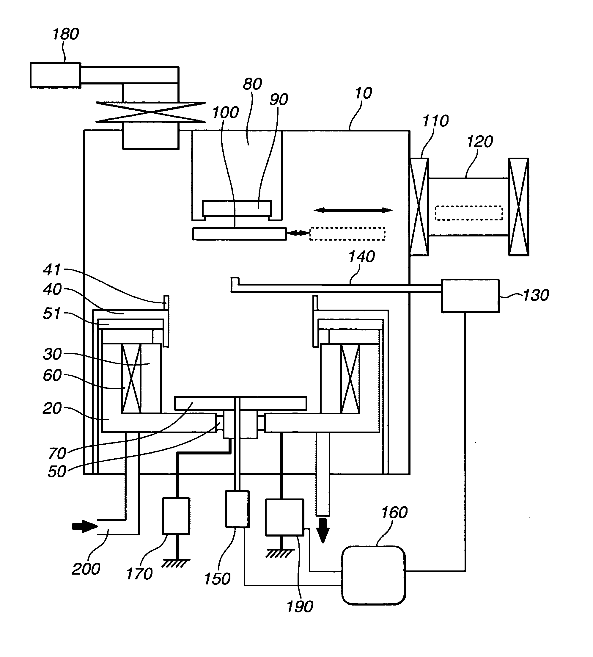
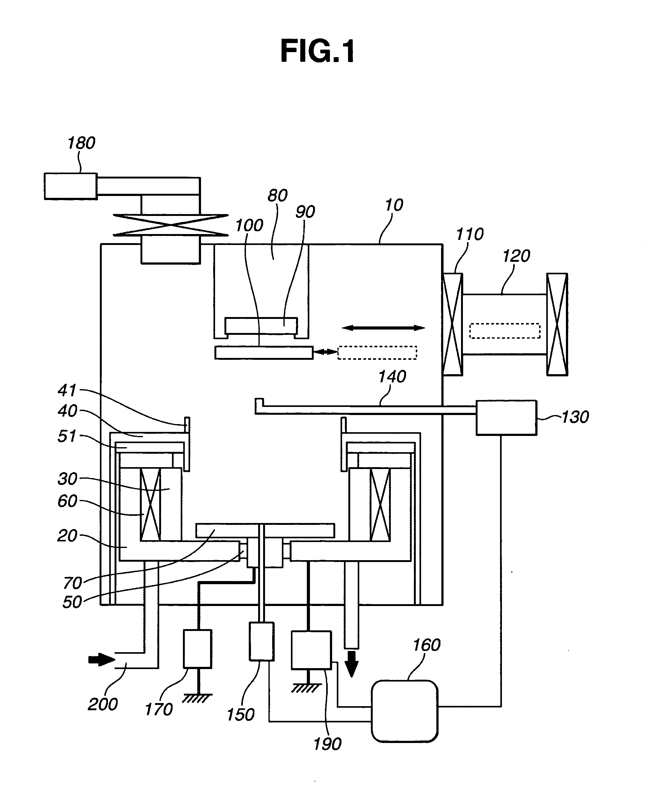
[0060] A first example of the present invention directed to a DC sputtering apparatus will be described with reference to the drawings.

[0061]FIG. 1 illustrates a cross section of a DC magnetron sputtering apparatus according to the first example. As illustrated in FIG. 1, the sputtering apparatus is provided with a vacuum chamber 10 for keeping an inside of the apparatus under an approximately vacuum condition, and an evacuating sys...


PUM

PropertyMeasurementUnit
Volumetric flow rateaaaaaaaaaa
Speedaaaaaaaaaa

Abstract

In a reactive sputtering apparatus, an inert-gas supplying hole is provided in a movable target unit whose one end is open and whose conductance is controlled, and a reactive gas containing at least fluorine or oxygen can be supplied to a space between the target and a substrate. The apparatus is constructed so as to emit the reactive gas toward the substrate. A reactive-gas emitting location is in the space between the target and the substrate such that a concentration of the reactive gas on the substrate surface can be maintained at a higher level. When the target is moved, a reactive-gas emitting port is moved or the reactive-gas emitting location is changed. The concentration of the reactive gas on the substrate surface can be effectively kept constant, and a high-quality optical thin film can be formed.

Description

BACKGROUND OF THE INVENTION [0001] 1. Field of the Invention [0002] The present invention relates to a reactive sputtering method, and more particularly to a reactive sputtering method that can be suitably used for formation of optical thin films, such as an antireflection film and a dielectric multi-layer mirror, usable in optical components for a visible wavelength range and an ultraviolet wavelength range, for example. [0003] 2. Description of the Related Art [0004] Conventionally, when optical thin films, such as an antireflection film and a mirror, are formed, a vacuum evaporation method is chiefly used in which a film-forming material is heated in a vacuum using an electron beam or the like, and the material is evaporated and deposited on a substrate. [0005] In general, an antireflection film, a mirror and the like include multi-layers or the like formed of either of a low-refractive-index material, such as a magnesium fluoride (MgF2), and a high-refractive-index material, suc...

Claims


Application Information

Patent Timeline
IPC IPC(8): G02B5/08C23C14/00C23C14/06C23C14/32C23C14/34C23C14/35G02B1/11H01J37/34
CPCC23C14/0057C23C14/0068C23C14/0694Y02T50/67F02D41/1456H01J37/3405H01J37/3485C23C14/35Y02T50/60
Inventor SUZUKI, YASUYUKITERANISHI, KOJI
Owner CANON KK
Why Eureka
Try Eureka