
Method and device for the removal of partially protein bound substances

Active Publication Date: 2005-06-02
GAMBRO LUNDIA AB
View PDF18 Cites 33 Cited by
  • Summary
  • Abstract
  • Description
  • Claims
  • Application Information

AI Technical Summary

Benefits of technology

[0019] The effect of ultrafiltration is also neglected in equations 3 and 4. For dissolved substances ultrafiltration is known to increase clearance by about ⅓to ½of the ultrafiltration rate, which usually means an increase of a few per cent. For carrier bound substances the effect of ultrafiltration is more complicated. Ultrafiltration in itself does not change the concentration in the remaining blood, and the carrier bound fraction of the substance is therefore unavailable for removal by pure ultrafiltration. Another effect of ultrafiltration is to decrease the flow of plasma, which makes it easier to decrease the plasma concentration of the substance. At the same time the blood becomes more concentrated, so that the concentration of the carrier also increases. This will increase the binding ratio α further, which tends to decrease the removal. The total effect of ultrafiltration on removal of carrier bound substances is probably less than for non bound substances.
[0027] Since in these cases the blood flow rate often is not the limiting factor, it may even be possible to lower the blood flow rate. The important factor is still to increase the membrane mass transfer coefficient koA (or LpA for hemofiltration) and the dialysis fluid flow rate, and the blood flow rate may then be lowered at least down to a fraction of 1 / α of the largest of these two. Such an action could limit any detrimental effects on the blood vessels that may be caused by removing large quantities of blood. Thus, patients intoxicated by drugs or other toxins may be treated by the method according to the present invention by inserting needles or catheters in a large but superficial blood vessel such as the Vena Cephalica, where a blood flow rate in the range of 50 ml / min can be obtained.
[0028] The lower blood flow rate may also increase the efficiency of the procedure by allowing a longer residence time of the blood in the dialyzer in cases where the equilibrium between the bound and dissolved fractions of the substances has a time delay. The dialysis fluid flow rate and koA should still be kept above 2000 ml / min, and preferably above 5000 ml / min or even higher. In hemofiltration LpA needs to be large enough to allow the necessary ultrafiltration rate with the high dialysis fluid flow rate at a moderate pressure gradient.
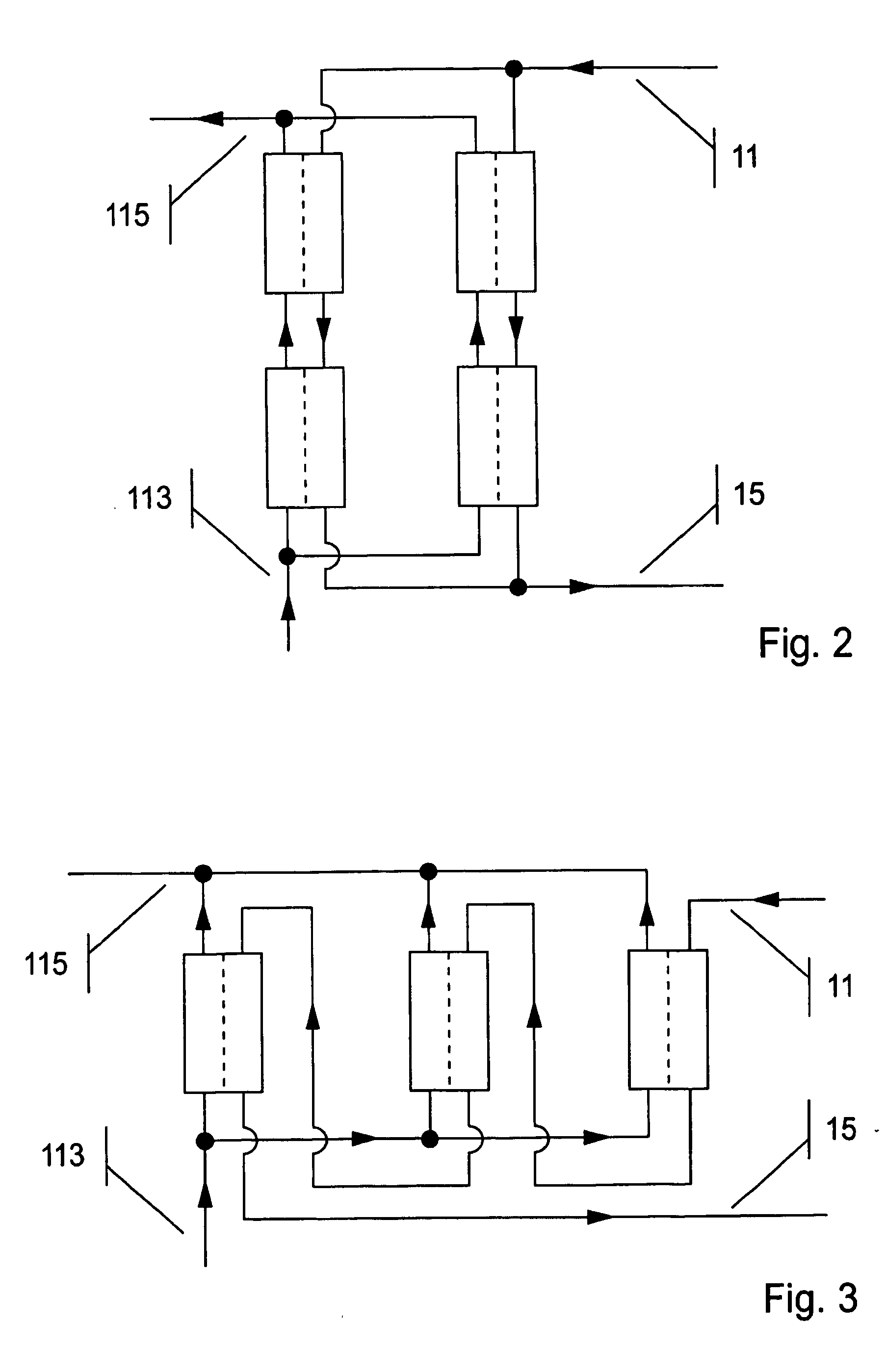
[0029] The membrane area, which is proportional to koA and LpA, can easily be increased either by using several standard dialysis filters in a series or in a parallel configuration, or combinations thereof, or by using specially designed filters with increased membrane area.
[0039] In a further embodiment of the present invention a carrier such as albumin is added to the large dialysis fluid flow and the large membrane is primed with the same or other carrier. The carrier is e.g. serum albumin. The concentration of serum albumin is preferably above 10 g / l. This embodiment of the invention is advantageous where very strongly bound substances are to be removed or where a ratio between bound and dissolved substances is exceptionally high.
[0040] In still a further embodiment of the invention a large dialysis fluid flow rate of about 4000 ml / min could be combined with a large membrane having a KoA of about 4000 ml / min and a concentration of a carrier such as serum albumin which is about 5 g / l. This embodiment is advantageous as the concentration of expensive albumin is limited while the effect of the dialysis treatment is kept on an acceptable level.

Problems solved by technology

In prior art, the procedure, thus, becomes expensive and slow as well as cumbersome, and there is a need for a simpler way to remove carrier bound substances from blood.

Method used


Image

  • Method and device for the removal of partially protein bound substances
  • Method and device for the removal of partially protein bound substances
  • Method and device for the removal of partially protein bound substances

Examples


Embodiment Construction

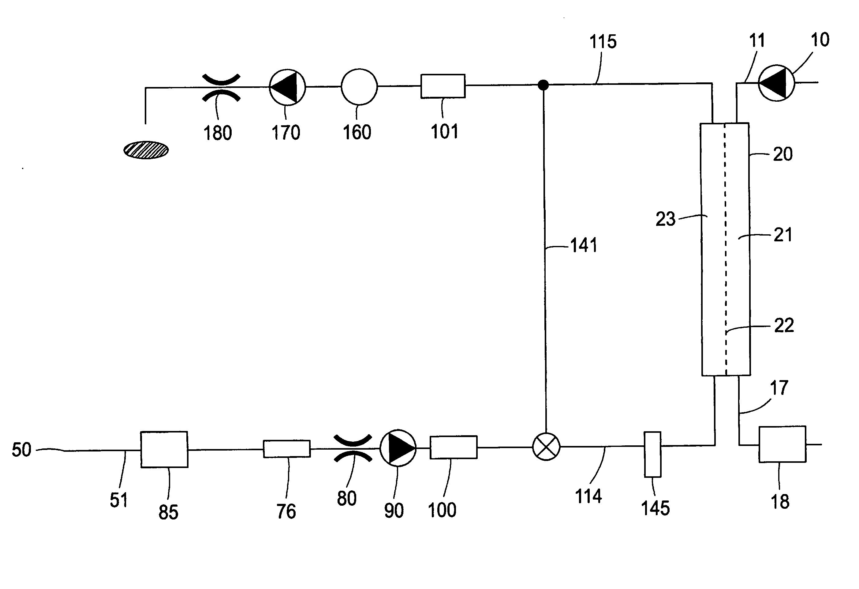
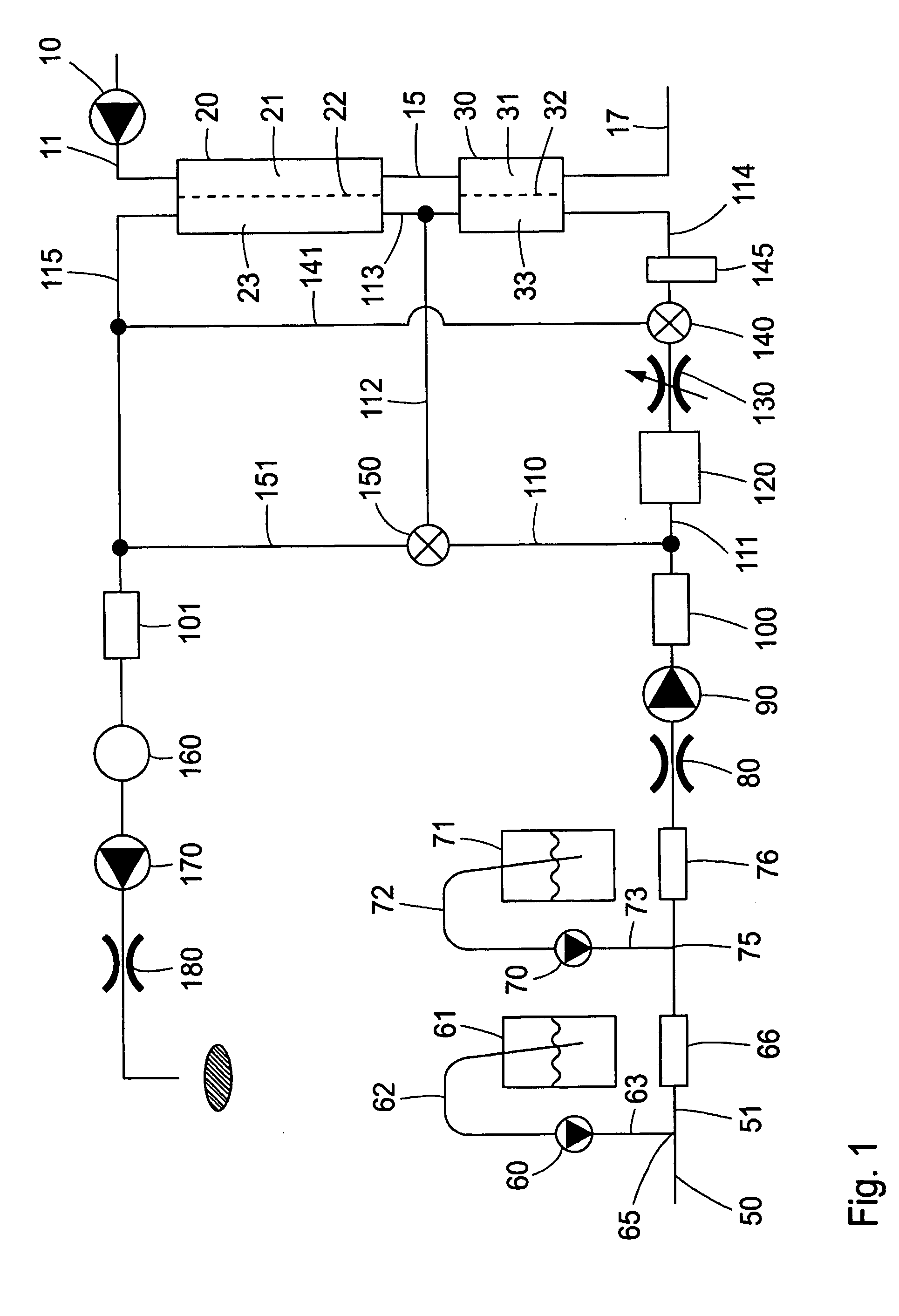
[0047] A first embodiment of the invention is shown in FIG. 1, which schematically shows a system with a close resemblance to a standard system for hemodialysis. Blood is transported with the help of a pump 10 from the patient via an arterial blood line 11 through the blood compartment 21 of a large dialyzer 20, and then via blood line 15 into the blood compartment 31 of a smaller dialyzer 30. It is then returned to the patient via blood line 17. Semipermeable membranes 22 and 32 in dialyzers 20 and 30, respectively, separate the blood compartments 21 and 31, respectively, from the dialysate compartments 23 and 33, respectively.

[0048] The pore size of the semipermeable membranes 22 and 32 should be chosen large enough to allow the passage of the toxins that are to be removed, the size of which in some cases are several thousand Daltons. The membranes should, on the other hand, effectively prevent the passage of carriers such as albumin, which has a size of about 66000 Daltons. Thes...


PUM

PropertyMeasurementUnit
Fractionaaaaaaaaaa
Fractionaaaaaaaaaa
Flow rateaaaaaaaaaa

Abstract

A method and a device to increase the efficiency of dialysis for the removal from blood of substances that are more or less tightly bound to carriers such as albumin. According to the invention this is accomplished by a simultaneous significant increase of the flow rate of the dialysis fluid and of the area of the membrane that separates the blood from the dialysis fluid, compared to conventional dialysis.

Description

FIELD OF THE INVENTION [0001] This invention relates to a method and a device for increasing the efficiency of dialysis for the removal of substances from a biological fluid such as blood, which substances are more or less tightly bound to carriers such as albumin. BACKGROUND [0002] For people who have lost all or most of their kidney or liver functions, it is necessary to find alternative ways of cleaning the blood. One common alternative is dialysis, in which the waste products in the blood are transported across a membrane to a cleaning fluid. In hemodialysis, the most common form of dialysis, blood is removed from the body, and is led to an external device, the dialyzer, which contains a membrane with blood flowing on one side and a dialysis fluid flowing on the other side of the membrane. The blood is then returned to the body. Due to the concentration difference between the blood and the dialysis fluid across the membrane, waste products in the blood will be transported by dif...

Claims


Application Information

Patent Timeline
IPC IPC(8): A61M1/16A61M1/36A61M1/34B01D61/24
CPCA61M1/16A61M1/1692A61M1/1696A61M1/3465A61M1/1647A61M1/165A61M1/3431B01D61/243A61M1/1633A61M2205/3317A61M2205/3324A61M2205/3334A61M2205/3368A61M2205/3393A61M1/1607A61M1/341A61M1/3623B01D61/28B01D61/244
Inventor STERNBY, JANSTERNBY, BERIT
Owner GAMBRO LUNDIA AB
Learn More