
Method for treating exhaust gas

a technology for exhaust gas and treatment process, which is applied in the direction of electrical equipment, fluid pressure measurement, casing/lining, etc., can solve the problems of large volume of gas used in fabrication processes, inability to directly emit into, and harmful gases, etc., to achieve safe and energy-saving effects

Inactive Publication Date: 2005-06-02
SHOWA DENKO KK +1
View PDF8 Cites 8 Cited by
  • Summary
  • Abstract
  • Description
  • Claims
  • Application Information

AI Technical Summary

Benefits of technology

[0015] In light of this background, it is an object of the present invention to provide an abatement process and system which allows treatment of exhaust gases emitted from semiconductor fabrication processes, containing fluorine gas or halogen fluoride gases at high concentrations or in large amounts, and which is safe and energy efficient and can accomplish abatement in a more efficient manner.
[0016] As mentioned above, when fluorine gas or halogen fluoride gas is used in a semiconductor fabrication process the exhaust gas is treated alone by a special abatement system, but the process of the invention overcomes the problems described above by allowing semiconductor devices to be increased in size and complexity and be provided with multiple functions, while reducing the installation space for the abatement system.

Problems solved by technology

The exhaust gas emitted from various steps in the fabrication of semiconductors contains gases such as semiconductor material gas, etching gas or cleaning gas, and these gases are often harmful.
They sometimes include environmentally unfriendly gases and, therefore, exhaust gas containing such components cannot be directly emitted into the atmosphere.
Recent years have seen an increasing diversity of harmful components contained in exhaust gases emitted from semiconductor fabrication processes, as well as markedly larger sizes of wafers and liquid crystal panels and correspondingly larger fabricating apparatuses, resulting in vastly greater volumes of gases used in the fabrication processes.
In addition, with increasing use of multi-chambers for sheet-fed apparatuses and the concomitant greater complexity of fabrication processes, it often becomes necessary to simultaneously treat large volumes of exhaust gases from different pathways, or to safely treat exhaust gases, streaming in the same pathway while changing the time cycle, with vastly differing properties using the same abatement system.
However, particularly in the case of combustion-type abatement systems, the exhaust gas emitted from the semiconductor fabrication process is subjected to combustion treatment at high temperature together with fuel gases such as utility gas, LPG, methane or the like and with supporting gases such as air and oxygen, and this results in the generation of NOx gases, as by-products, from the elemental nitrogen in the exhaust gas or the nitrogen gas in the air.
Nevertheless, fluorine gas or halogen fluoride gases are highly active, strong oxidizers with high chemical reactivity and therefore often react with oxidizing substances at ordinary temperature resulting in ignition, while they are also highly corrosive to apparatus materials.
The apparatus materials must therefore be strictly selected from among specific highly corrosion-resistant metals, and be free from oils and water; moreover, tetrafluoroethylene resins which are widely used as highly corrosion-resistant resins for semiconductor fabrication apparatuses are often unsuitable for the given conditions of use.
All such methods, however, have a drawback in that they do not allow treatment of exhaust gas containing high concentrations of fluorine gas or halogen fluoride gases.
Additional problems encountered when employing a wet abatement system such as an alkali scrubber in cases of large volumes of fluorine gas or halogen fluoride gases, is that the absorption tower must be increased in size, waste treatment of the absorption solution becomes complicated, and running costs are higher.
With dry decomposition abatement systems or adsorption removal abatement systems, not only is it difficult to set up large flow abatement systems, but the increased frequency of replacement of the solid decomposer and adsorbent results in drastically higher operating cost, while the added maintenance procedures tend to lead to safety management problems.

Method used


Image

  • Method for treating exhaust gas
  • Method for treating exhaust gas

Examples


example 1

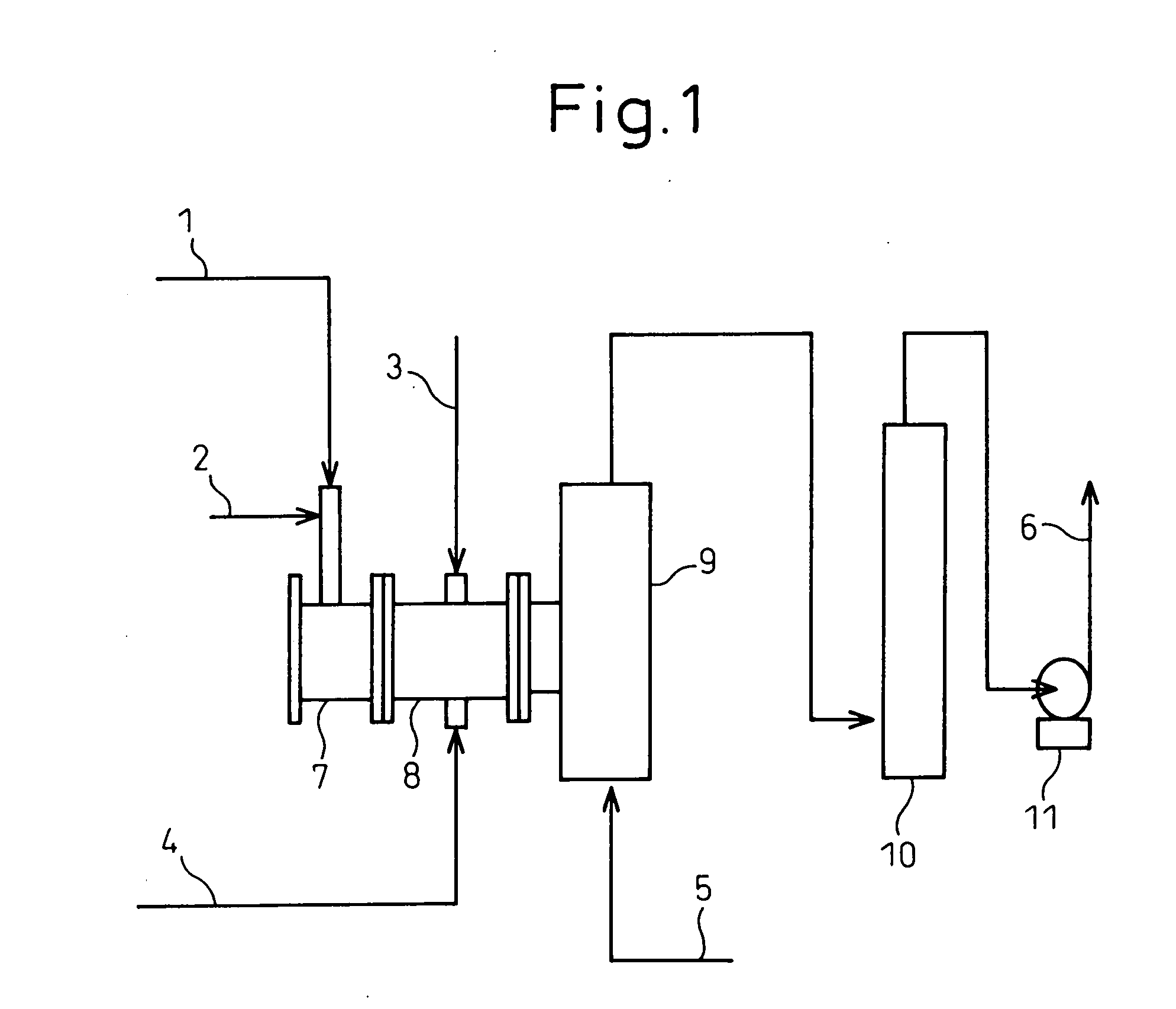
[0044] The stainless steel combustion chamber of a combustion-type abatement system and the parts surrounding it were subjected to nickel plating and fluoride passivation treatment, and a combustion-abatement experiment was conducted using fluorine gas. The combustion-type abatement system operating conditions and fluorine introduction conditions are shown in Table 1, and the results of compositional analysis of the exhaust gas emitted after combustion and abatement are shown in Table 2. The combustion chamber temperature was measured with a thermocouple attached to the combustion chamber outer wall. The nitrogen monoxide and nitrogen dioxide concentrations in the exhaust gas after combustion were measured with a gas detector tube, and the hydrogen fluoride gas concentration was measured by infrared spectroscopy. The nitrogen trifluoride was measured using a detector. Sampling was performed with an aqueous potassium iodide solution, the fluorine gas concentration of the sample solut...


PUM

PropertyMeasurementUnit
temperatureaaaaaaaaaa
flow rateaaaaaaaaaa
temperatureaaaaaaaaaa

Abstract

Exhaust gas containing fluorine gas or halogen fluoride gas emitted from etching or cleaning steps is burned in a combustion chamber having a fluoride passivation film formed on its surface. It is possible to treat exhaust gas emitted from semiconductor fabrication processes which contains fluorine gas or halogen fluoride gas in high concentrations or large volumes, while abatement treatment can be accomplished safely and efficiently with less energy usage.

Description

TECHNICAL FIELD [0001] The present invention relates to an exhaust gas treatment process and treatment apparatus. More particularly, the invention relates to a process and apparatus for treatment of an exhaust gas, containing fluorine gas or halogen fluoride gas, which is emitted from the etching or the cleaning steps of semiconductor fabrication processes, and to a semiconductor device fabrication process which employs the process and apparatus. BACKGROUND ART [0002] The exhaust gas emitted from various steps in the fabrication of semiconductors contains gases such as semiconductor material gas, etching gas or cleaning gas, and these gases are often harmful. They sometimes include environmentally unfriendly gases and, therefore, exhaust gas containing such components cannot be directly emitted into the atmosphere. [0003] Methods for exhaust gas treatment are widely known, and include: [0004] (1) wet abatement methods whereby neutralizing agents such as caustic soda (sodium hydroxid...

Claims


Application Information

Patent Timeline
Patent Type & Authority Applications(United States)
IPC IPC(8): B01D53/68F23G7/06H01L21/302
CPCF23J2215/30F23G7/065F23G7/06
Inventor TAGUCHI, HIROYASUHOSHINO, YASUYUKIPARK, BYOUNG-SUPJIN, BINGZHE
Owner SHOWA DENKO KK
Learn More