
Methods and systems for the rapid detection of concealed objects

a technology of concealed objects and detection methods, applied in the field of microwave imaging systems, can solve the problems of compromising detection performance, affecting the accuracy of detection, and the dual-energy method not readily allowing the calculation of the actual atomic number, so as to reduce the frequency of false alarms, increase throughput, and accurately identify the nature

Inactive Publication Date: 2005-05-19
RAPISCAN SYST INC (US)
View PDF15 Cites 87 Cited by
  • Summary
  • Abstract
  • Description
  • Claims
  • Application Information

AI Technical Summary

Benefits of technology

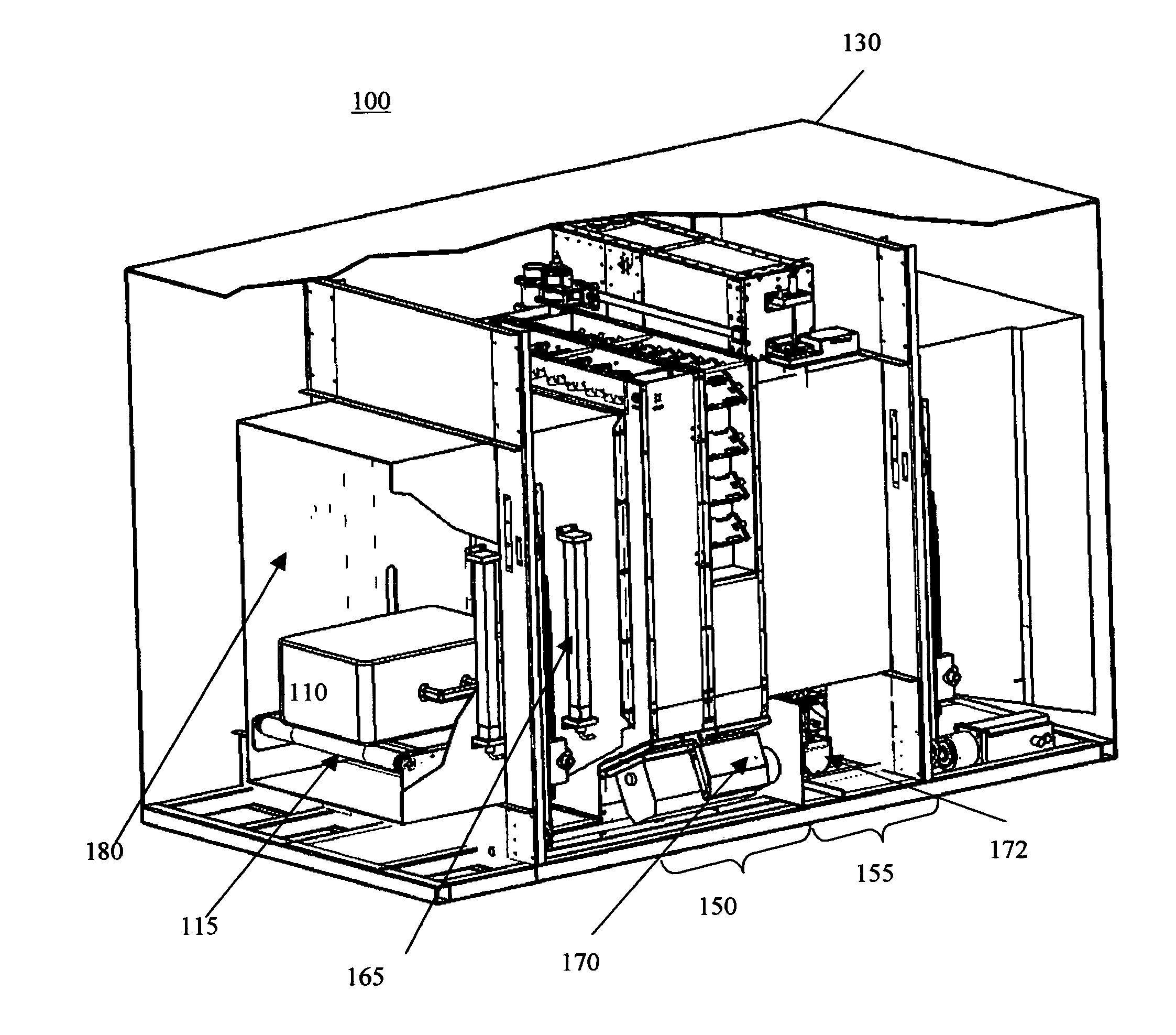
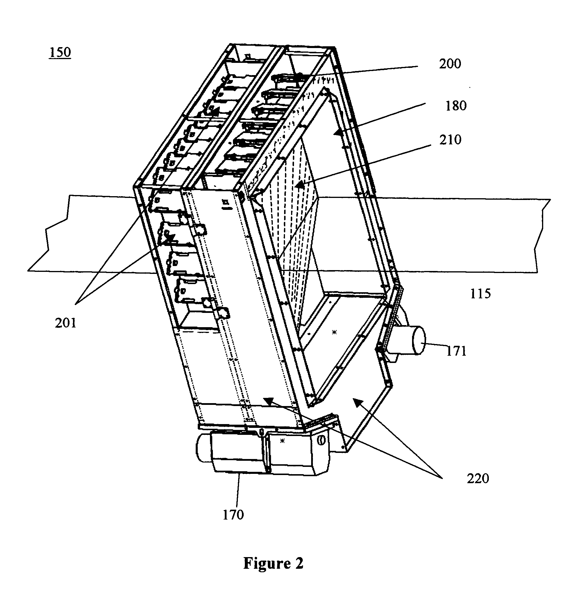
The present invention provides an improved scanning process for detecting threats in bags and packages. The process involves pre-selecting potential threat locations and using microwave arrays to accurately identify threats. The system is compact, automated, and requires minimal operator skill. It can detect small amounts of threat material and is relatively insensitive to distortions in the image caused by metallic clutter. The system can also screen for metal in real-time and provide three-dimensional positional information. The invention also includes an integrated security scanning system with multiple screening systems that can detect threats in different ways.

Problems solved by technology

These radiographs are often difficult to interpret because objects are superimposed.
With a large number of such radiographs to be interpreted, and with the implied requirement to keep the number of false alarms low, operator fatigue and distraction can compromise detection performance.
However, the dual-energy method does not readily allow for the calculation of the actual atomic number of the concealed ‘threat’ itself, but rather yields only an average atomic number that represents the mix of the various items falling within the X-ray beam path, as the contents of an actual luggage is composed of different items and rarely conveniently separated.
Thus dual-energy analysis is often confounded.
Even if the atomic number of an item could be measured, the precision of this measurement would be compromised by X-ray photon noise to the extent that many innocuous items would show the “same” atomic number as many threat substances, and therefore the atomic number in principle cannot serve as a sufficiently specific classifier for threat versus no threat.
However, conventional CT systems take considerable time to perform multiple scans, to capture data, and to reconstruct the images.
The throughput of CT systems is generally low.
Coupled with the size and expense of CT systems this limitation has hindered CT use in applications such as baggage inspection where baggage throughput is an important concern.
In addition, CT alarms on critical mass and density of a threat, but such properties are not unique to explosives.
CT based systems suffer from high false alarm rate.
Each of the prior art systems and methods, however, suffer from low processing rates because the scatter interaction cross sections are relatively small and the exposure times required to obtain useful diffraction spectra are long, in the range of seconds and minutes.
However, the use of CT scanning is still inefficient, not threat specific, and does not allow for rapid scanning of objects.
The disclosed system does not, however, address critical problems that arise in the course of applying a scatter probe to a selected suspicious region, including the accurate identification of a suspicious region, correction of detected data, and the nature of processing algorithms used.
One potential weakness of the technique is that, with carefully designed electromagnetic shielding, the materials which it is being used to detect can be rendered undetectable.
This potential problem is mitigated by the fact that such shielding consists of conductive (typically metal) volumes that must completely encapsulate the item to be detected.
However, the presence of a conductive loop around luggage means that the simplest forms of inductive metal detector would have limited performance.

Method used


Image

  • Methods and systems for the rapid detection of concealed objects
  • Methods and systems for the rapid detection of concealed objects
  • Methods and systems for the rapid detection of concealed objects

Examples


second embodiment

[0106] In a second embodiment, the transmission detector array functions as an imaging detector to provide precise attenuation data for certain areas in containers, like container wall areas, where contraband can be hidden. When the circular beam is centered on an edge of a container, the edge of the container can be imaged in good detail, and can help analyze the edges for concealed threats.

third embodiment

[0107] In a third embodiment, transmission detector measurements can be used to determine whether the inspection region is, in fact, the same target region previously identified in the first stage scan. If the transmission data correlates with X-ray characteristics different than those obtained in the first stage scan, the relative positioning of the second stage scanning system and the object under inspection may be modified until the transmission data correlates with the same material characteristics that was identified in the first stage scan.

fourth embodiment

[0108] In a fourth embodiment, transmission detector data are also being used to simplify the algorithm-training procedure of the system, as described below, in particular the collection of threat material properties with irregularly shaped threat samples, like sticks of dynamite.

[0109] It should be noted that it would appear because the scatter radiation path and transmission path differ downstream from the scatter volume, there would be inconsistencies in the data when scatter and transmission data are combined. This inconsistency is one example of a number of partial volume effects, solutions for which are addressed herein. However, the inconsistencies are not significant and can be tolerated without encountering significant performance degradation of the system as a whole. As shown, FIG. 4 is not an isometric schematic and, in reality, the scatter angle is preferably about 3 degrees, and the real path differences are comparatively smaller.

[0110] d. Positioning Inspection Region...


PUM

PropertyMeasurementUnit
scatter angleaaaaaaaaaa
volumeaaaaaaaaaa

Abstract

The present invention provides for an improved scanning process having microwave arrays comprised of microwave transmitters in radiographic alignment with microwave receivers. The microwave array emits controllably directed microwave radiation toward an object under inspection. The object under inspection absorbs radiation in a manner dependent upon its metal content. The microwave radiation absorption can be used to generate a measurement of metal content. The measurement, in turn, can be used to calculate at least a portion of the volume and shape of the object under inspection. The measurement can be compared to a plurality of predefined threats. The microwave screening system can be used in combination with other screening technologies, such as NQR-based screening, X-ray transmission based screening, X-ray scattered based screening, or Computed Tomography based screening.

Description

CROSS-REFERENCE TO RELATED APPLICATION(S) [0001] This application is a continuation-in-part of co-pending U.S. patent application Ser. No. 10 / 662,778, filed on Sep. 15, 2003.FIELD OF THE INVENTION [0002] The present invention relates generally to a microwave imaging system that is compatible with X-ray and Nuclear Quadrupole Resonance (NQR) based methods and systems for detection of concealed threats, and threat resolution, and more specifically to improved methods and systems, using dual stage scanning to process luggage for faster inspection with reduced false alarm rate. BACKGROUND OF THE INVENTION [0003] Conventional X-ray systems produce radiographic projection images, which are then interpreted by an operator. These radiographs are often difficult to interpret because objects are superimposed. A trained operator must study and interpret each image to render an opinion on whether or not a target of interest, a threat, is present. With a large number of such radiographs to be in...

Claims


Application Information

Patent Timeline
Patent Type & Authority Applications(United States)
IPC IPC(8): G01V5/00
CPCG01V5/0016G01V11/00G01V5/0025G01V5/22G01V5/222G01R27/06G01N22/00G01F23/284
Inventor PESCHMANN, KRISTIAN R.MANN, KENNETH ROBERT
Owner RAPISCAN SYST INC (US)
Learn More