
Semiconductor device having multilayer interconnection structure and manufacturing method thereof

a technology of interconnection structure and semiconductor device, which is applied in the direction of semiconductor device details, semiconductor/solid-state device devices, electrical apparatus, etc., can solve the problems of high risk of short-circuit between neighboring circuit patterns, easy short-circuit between neighboring conductive patterns, and difficulty in ensuring a safe distance between patterns in the horizontal direction, so as to reduce the stress of an interlevel dielectric layer and prevent short-circuits. , the effect of adequate outgassing

Inactive Publication Date: 2005-03-31
SAMSUNG ELECTRONICS CO LTD
View PDF21 Cites 4 Cited by
  • Summary
  • Abstract
  • Description
  • Claims
  • Application Information

AI Technical Summary

Benefits of technology

[0012] It is a second objective of the present invention to provide a semiconductor device capable of obtaining a sufficient contact margin between upper and lower studs.
[0013] It is a third objective of the present invention to provide a semiconductor device capable of preventing short-circuits between neighboring conductive patterns while obtaining a sufficient contact margin between upper and lower studs.
[0014] It is a fourth objective of the present invention to provide a semiconductor device capable of reducing stress of an interlevel dielectric (ILD) layer, caused by an etch stopper.
[0015] It is a fifth objective of the present invention to provide a semiconductor device capable of adequate outgassing of impurities while reducing stress in circuits.
[0016] It is a sixth objective of the present invention to provide a semiconductor device capable of preventing deterioration of the adhesion characteristics of a gate insulating layer and a semiconductor substrate.

Problems solved by technology

However, a conventional landing pad or tap assists the alignment of the plug, and due to the width being larger than that of the stud (or plug), there is a high risk that a short-circuit may occur between neighboring circuit patterns.
However, the following problems arise in a conventional multilayer interconnection structure.
First, in the mentioned prior art, a landing pad is not used.
Thus, a short-circuit can readily occur between neighboring conductive patterns.
In particular, since circuit layers are very densely arranged on the peripheral region, it is not easy to secure a safe distance between patterns in the horizontal direction that are formed on the same level.
As a result, the adhesion characteristics between the semiconductor substrate 100 and the gate insulating layer are adversely affected.

Method used


Image

  • Semiconductor device having multilayer interconnection structure and manufacturing method thereof
  • Semiconductor device having multilayer interconnection structure and manufacturing method thereof
  • Semiconductor device having multilayer interconnection structure and manufacturing method thereof

Examples


embodiment 1

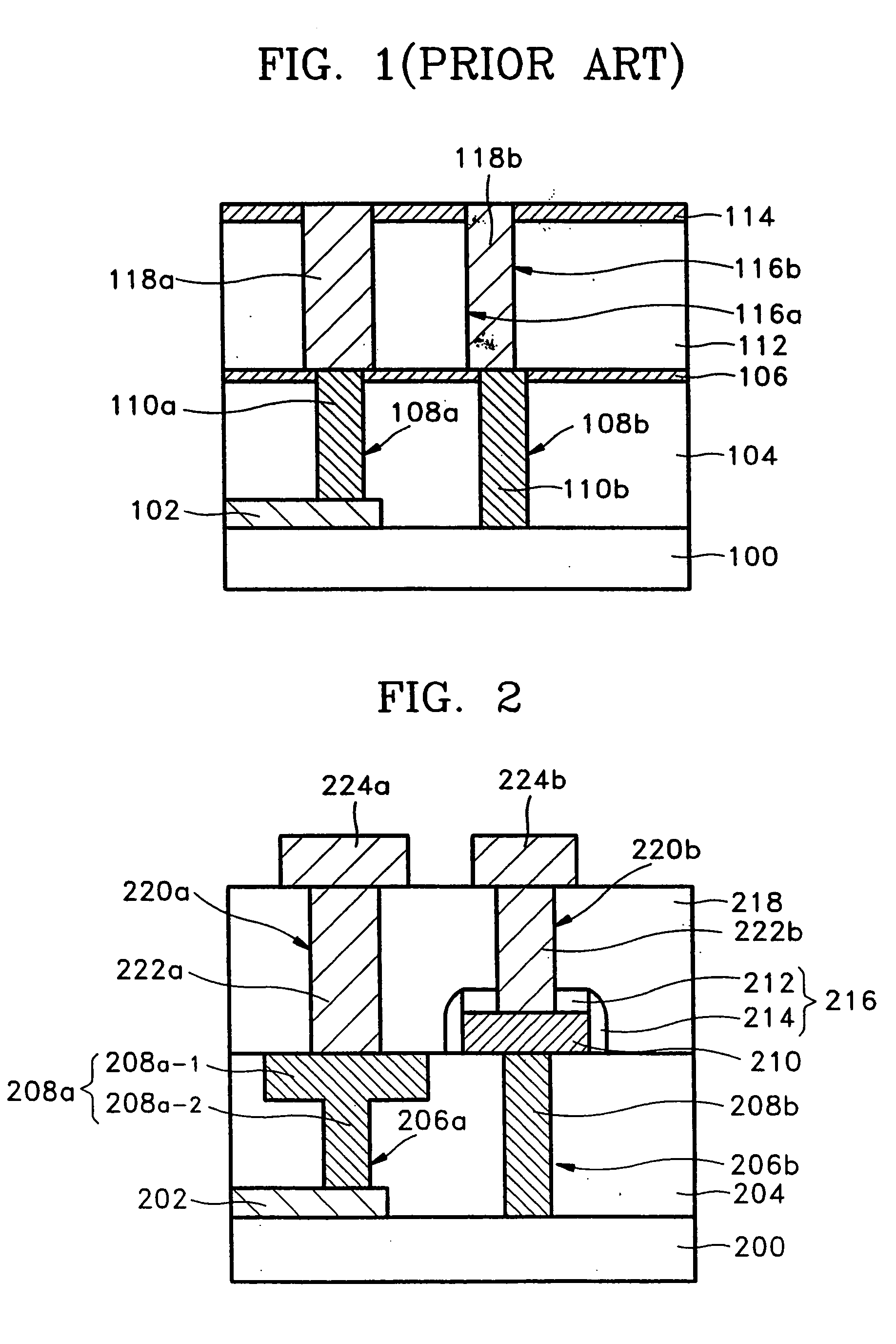
[0036]FIG. 2 is a sectional view of a semiconductor device according to an embodiment of the present invention, and the principles of the present invention will be described with reference to FIG. 2. A conductive pattern 202 is initially formed on a semiconductor substrate 200, and a first interlevel dielectric (ILD) layer 204 is formed on the conductive pattern 202. Lower stud holes 206a and 206b are formed in the first ILD layer 204 to expose portions of the conductive pattern 202 and the semiconductor substrate 200, and the lower stud holes 206a and 206b are filled with a conductive material, thereby forming lower studs 208a and 208b. Here, one lower stud 208a of the lower studs 208a and 208b has the width of an upper portion (hereinafter, an entrance part 208a-1) adjacent to the surface of the first ILD layer 204 larger than the width of a lower portion (hereinafter, a contacting part 208a-2) adjacent to the semiconductor substrate 200. Preferably, the width of the upper, entran...

embodiment 2

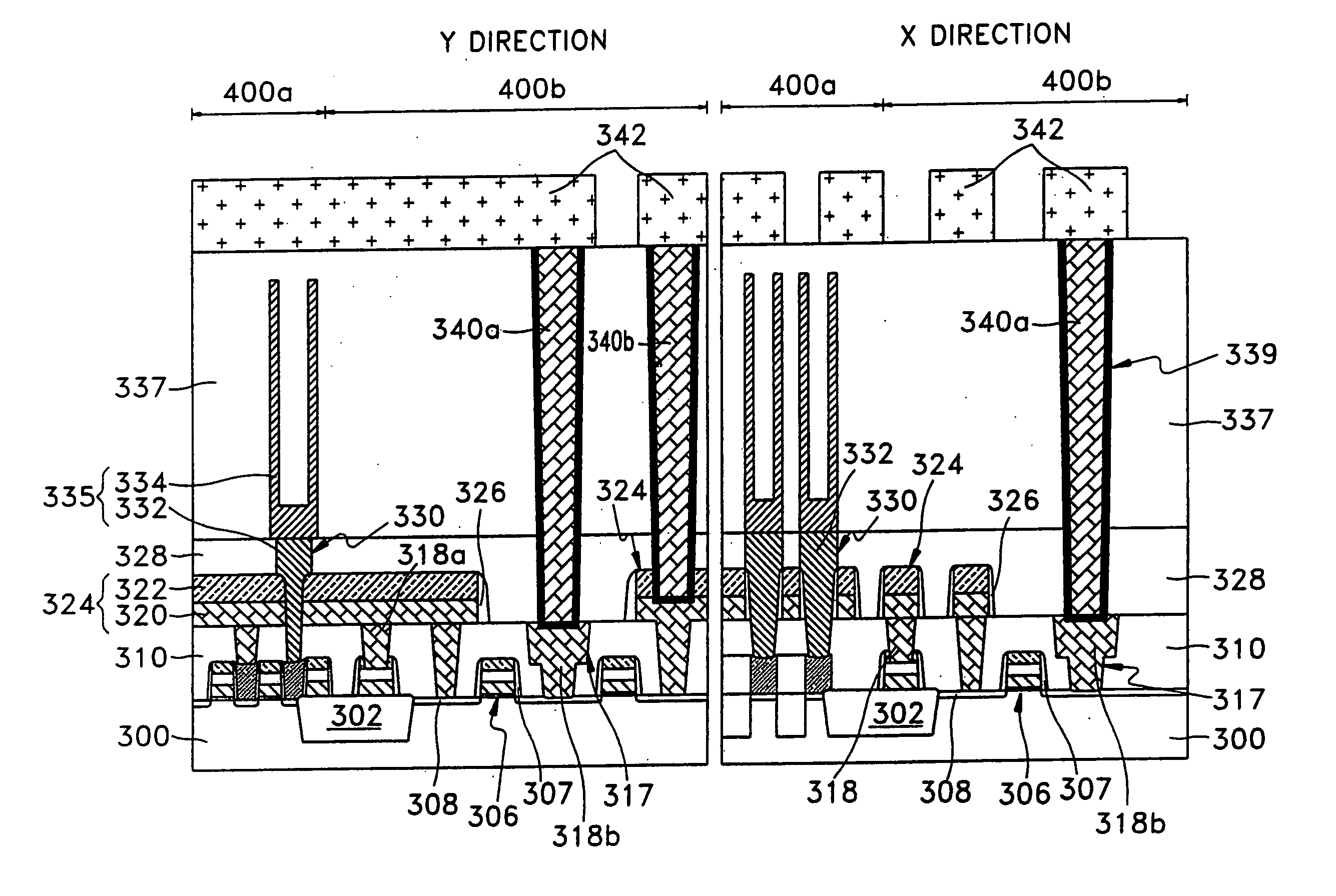
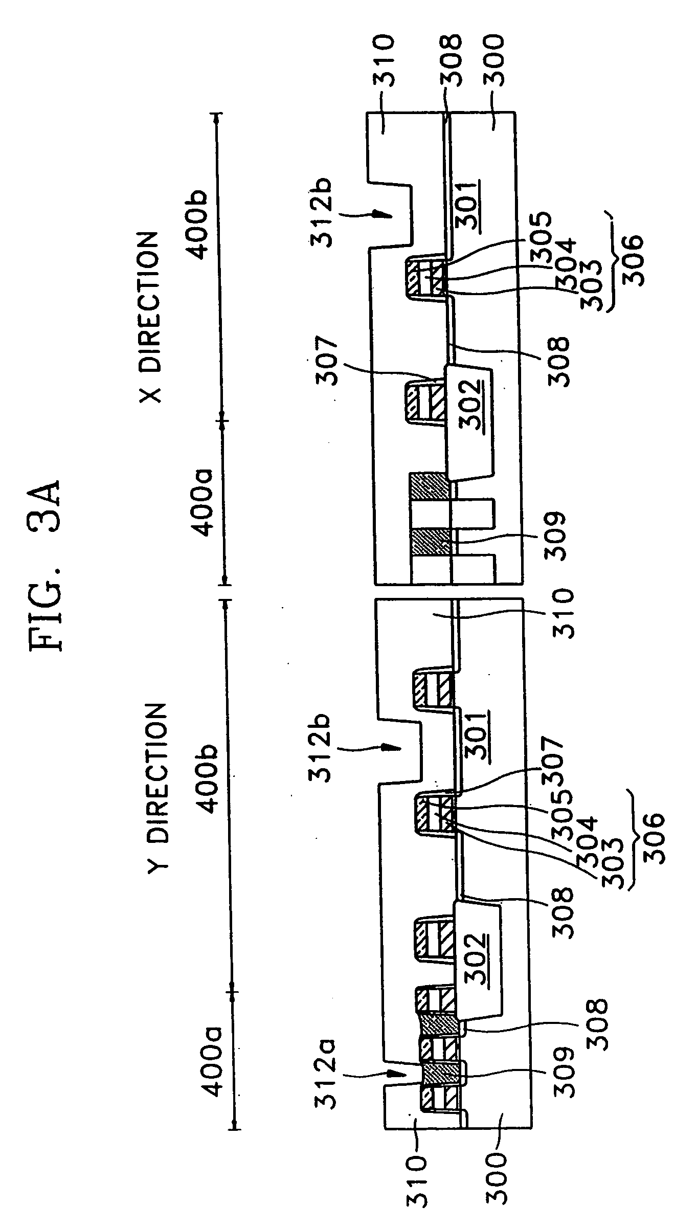
[0042] Typical applications of the present invention will be realized based on the drawings of FIGS. 3A through 3G. Here, FIGS. 3A through 3G are sectional views for each process of the multilayered interconnection structure of a memory device including a cell region and a peripheral region according to another embodiment of the present invention. In the drawings, “X” directions denote, for example, bit line-extended directions, and “Y” directions denote, for example, word line-extended directions.

[0043] Referring to FIG. 3A, a semiconductor substrate 300 on which a memory device is to be formed, is provided. A device isolation layer 302 is formed on a portion of the semiconductor substrate 300, thereby defining an active region 301. Also, a cell region 400a on which memory cells and bit lines are formed, and a peripheral region 400b on which peripheral circuits for assisting a memory cell region, such as peripheral interconnections and input / output circuits, are formed, are define...

embodiment 3

[0058]FIGS. 4A and 4B are sectional views for each process of the multilayer interconnection structure of the memory device including the cell region and the peripheral region according to another embodiment of the present invention. In this embodiment, since the steps of forming the gate electrodes 306, the junction region 308, the contact plug 309 on the semiconductor substrate 300 are the same as in the second embodiment, only the following steps will be described. Further, the same reference numerals are used in the same part of the embodiment as that of the second embodiment.

[0059] Referring to FIG. 4A, a first photoresist pattern (not shown) is formed on the first ILD layer 310 so that the selected gate electrodes 306 and the junction region 308 may be exposed. Here, a reticle (not shown) for forming the first photoresist pattern can be the same as that of the photoresist pattern 314 (see FIG. 3B). Next, the first ILD layer 310 is etched as the photoresist pattern, thereby fo...


PUM


Abstract

A semiconductor device and manufacturing method thereof include a semiconductor substrate, an interlevel dielectric (ILD) layer formed on the semiconductor substrate, a first contact stud formed in the ILD layer, having a width of an entrance portion adjacent to the surface of the ILD layer larger than the width of a contacting portion adjacent to the semiconductor substrate, and a second contact stud spaced apart from the first contact stud and formed in the ILD layer. The semiconductor device further includes a landing pad formed on the ILD layer to contact the surface of the second contact stud, having a width larger than that of the second contact stud. The second contact stud has a width of a contacting portion that is the same as that of an entrance portion. Also, at least one spacer comprising an etch stopper material is formed on the sidewalls of the landing pad and the etch stopper is formed on the landing pad. The entrance portion of the first contact stud has a width about 30-60% larger than that of the contacting portion.

Description

RELATED APPLICATIONS [0001] This application is a divisional of U.S. application Ser. No. 09 / 999,104, filed Oct. 31, 2001, which relies for priority upon Korean patent application number 01-6123, filed Feb. 8, 2001, the contents of which are herein incorporated by reference in their entirety.BACKGROUND OF THE INVENTION [0002] 1. Field of the Invention [0003] The present invention relates to a semiconductor device and manufacturing method thereof, and more particularly, to a semiconductor device having a multilayer interconnection structure and manufacturing method thereof. [0004] 2. Description of the Related Art [0005] In general, multilayered interconnection technology employs three-dimensional integrated circuits to more effectively utilize the surface area of the integrated circuits. Highly integrated memory devices having a large capacity equal to or greater than 1 gigabyte, for example, a dynamic random access memory (DRAM) device, can be designed by employing the multilayered...

Claims


Application Information

Patent Timeline
Patent Type & Authority Applications(United States)
IPC IPC(8): H01L21/28H01L21/768H01L23/485H01L23/522H10B12/00
CPCH01L21/76801H01L21/76804H01L21/76877H01L21/76895H01L23/485H01L2924/0002H01L23/5226H01L2924/00H01L21/28
Inventor YANG, WON-SUKKIM, KI-NAMJEONG, HONG-SIK
Owner SAMSUNG ELECTRONICS CO LTD
Learn More