
Thermal treatment apparatus and power generation module

Inactive Publication Date: 2005-03-31
CASIO COMPUTER CO LTD
View PDF4 Cites 15 Cited by
  • Summary
  • Abstract
  • Description
  • Claims
  • Application Information

AI Technical Summary

Benefits of technology

An advantage of the present invention is to provide a thermal treatment apparatus and a power generation module which enable the configuration to be simplified and heat loss in the furnace of the reformer to be reduced and which raise the temperature measurement precision.
is to provide a thermal treatment apparatus and a power generation module which enable the configuration to be simplified and heat loss in the furnace of the reformer to be reduced and which raise the temperature measurement precision.
A thermal treatment apparatus according to one aspect of the present invention is provided on a substrate, and the thermal treatment apparatus comprises:
a diffusion preventing layer which contacts one surface of the heat generating layer to prevent heat diffusion due to heat generation of the heat generating layer; and
a cohering layer disposed between the substrate and the diffusion preventing layer.
A power generation module according to another aspect of the present invention comprises:

Problems solved by technology

The fuel to be used for the fuel cell includes hydrogen, but it has handling and storing problems because it is in a gas state at room temperature.

Method used


Image

  • Thermal treatment apparatus and power generation module
  • Thermal treatment apparatus and power generation module
  • Thermal treatment apparatus and power generation module

Examples


Embodiment Construction

A best mode for carrying out the present invention will hereinafter be described with reference to the drawings. However, the scope of the invention is not limited to examples shown in the drawings.

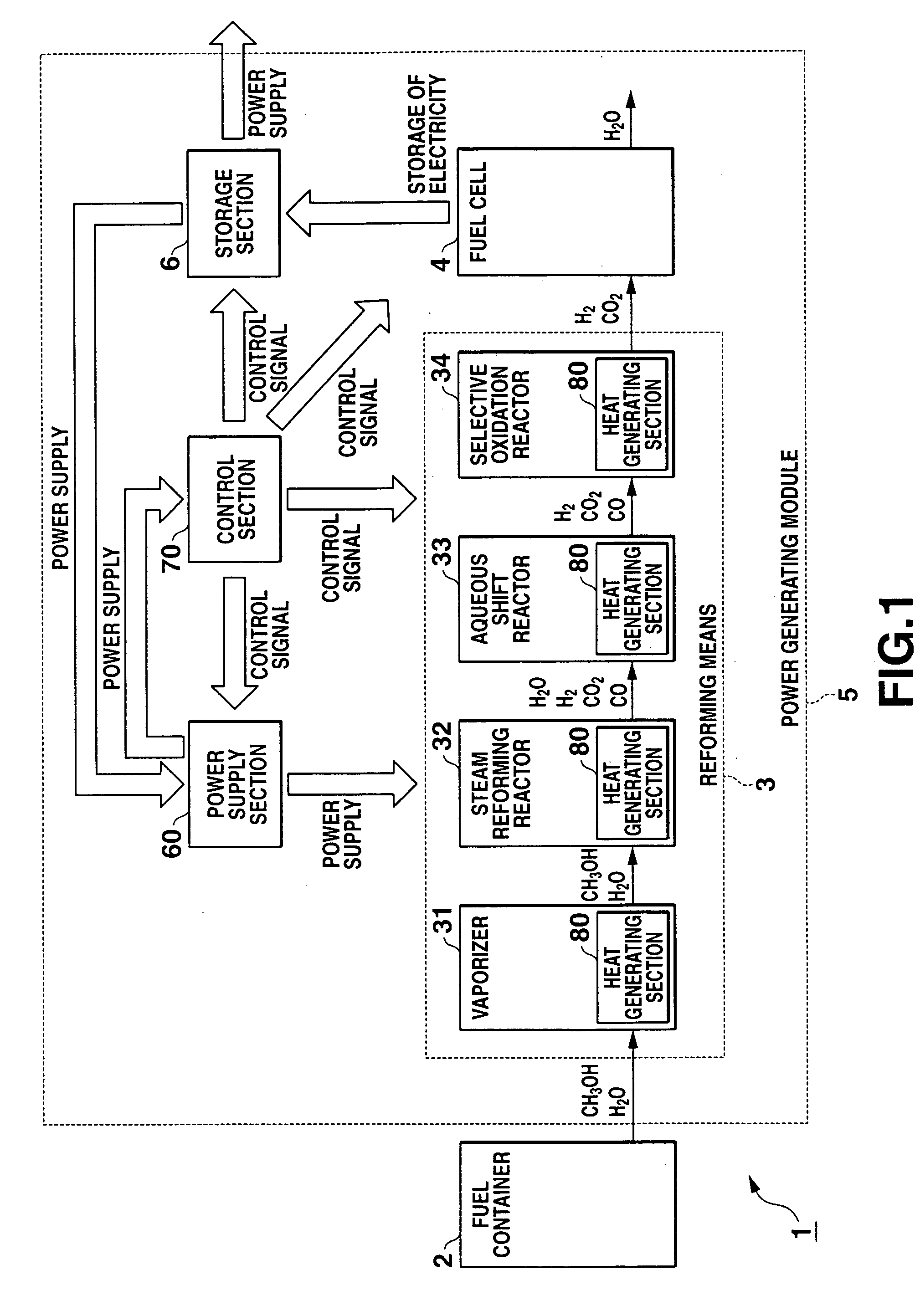
FIG. 1 is a block diagram showing a basic configuration of a power generation system 1 to which heat generating sections or heating sources 80 according to the present invention are applied, and FIG. 2 is a perspective view schematically showing an internal configuration by partially breaking the power generation system 1.

The power generation system 1 includes a fuel container 2 and a power generation module 5 which is removably attached to the fuel container 2. The power generation module 5 has a reforming means or section 3 (reformer) which reforms a chemical fuel (fuel to be heat-treated), a fuel cell 4 which generates electric power with the fuel reformed by the reforming means 3, and a storage section 6 which stores the electric power generated by the fuel cell 4 and outputs it as ...


PUM


Abstract

A thermal treatment apparatus provided on a substrate includes a heat generating section the section includes a heat generating layer, a diffusion preventing layer which contacts one surface of the heat generating layer to prevent heat diffusion due to heat generation of the heat generating layer, and a cohering layer disposed between the substrate and the diffusion preventing layer.

Description

CROSS-REFERENCE TO RELATED APPLICATIONS This application is based upon and claims the benefit of priority from prior Japanese Patent Application No. 2003-338469, filed Sep. 29, 2003; the entire contents of which are incorporated herein by reference. BACKGROUND OF THE INVENTION 1. Field of the Invention The present invention relates to a thermal treatment apparatus to perform a thermal treatment in a furnace. 2. Description of the Related Art Recently, it have been begun that fuel cells utilizing hydrogen as a fuel are applied to, for example, automobiles or portable devices as clean power supplies with high energy conversion efficiency. The fuel cell is equipment which electrochemically reacts a fuel with oxygen in the air to directly extract electric energy from chemical energy. The fuel to be used for the fuel cell includes hydrogen, but it has handling and storing problems because it is in a gas state at room temperature. If liquid fuels such as alcohols and gasoline are us...

Claims


Application Information

Patent Timeline
IPC IPC(8): B01J19/00F28F13/18H01M8/04H01M8/06
CPCB01J19/0093B01J2219/00783B01J2219/00835B01J2219/00873Y02E60/50F28F13/18H01M8/04007H01M8/0612B01J2219/00961B01J19/00B01J19/32H01M8/06
Inventor NOMURA, MASATOSHINAKAMURA, OSAMUTERAZAKI, TSUTOMUTAKEYAMA, KEISHI
Owner CASIO COMPUTER CO LTD
Learn More