
Method of making liquid crystal polymer films

a liquid crystal polymer and film technology, applied in the field of liquid crystal polymer film making, can solve the problems of increasing reducing the thermal expansion coefficient of the film

Active Publication Date: 2005-03-31
KURARAY CO LTD
View PDF33 Cites 21 Cited by
  • Summary
  • Abstract
  • Description
  • Claims
  • Application Information

AI Technical Summary

Benefits of technology

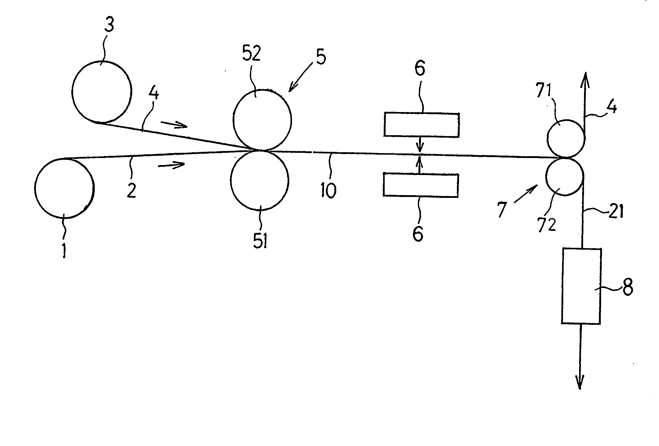
The present invention provides an improved method for manufacturing a thermotropic liquid crystal polymer film that has a controlled coefficient of thermal expansion and is useful as an electric insulating material for use with circuit boards such as flexible circuit boards or multilayered circuit boards. The method involves continuously heat treating the film while it is jointed to a support member and then separating it from the support member. The heat treatment is carried out at a specific temperature and for a specific duration of time to increase the thermal expansion coefficient of the film. The heating temperature is preferably between the melting point of the film and 15°C, but should not be lower than the melting point. The support member should have a higher coefficient of thermal expansion than the film to ensure the film does not deteriorate easily. The heating time should be between 5 to 60 seconds, with 10 to 30 seconds being preferred for optimal results.

Problems solved by technology

Specifically, it has hitherto generally been considered that the heat treatment of the thermotropic liquid crystal polymer film at a temperature lower than the melting point thereof results in reduction of the thermal expansion coefficient of the film, but the heat treatment of the thermotropic liquid crystal polymer film at a temperature higher than the melting point thereof results in increase of the thermal expansion coefficient of the film.

Method used


Image

  • Method of making liquid crystal polymer films
  • Method of making liquid crystal polymer films
  • Method of making liquid crystal polymer films

Examples


example 1

The thermotropic liquid crystal polymer film, obtained under Reference Example above, and a support member, which is an aluminum foil of 50 μm in thickness and having a thermal expansion coefficient S of 23×10−6 cm / cm / ° C., were supplied towards a continuous hot roll press apparatus including a heat resistant rubber roll, (having a hardness of 90 degree according to the JIS A) and a metal roll. As the thermotropic liquid crystal polymer film and the support member were passed through the nipping area of the continuous hot roll press with the thermotropic liquid crystal polymer film and the support member held in contact the heat resistant rubber roll and the metal roll, respectively, they were press-bonded together at 26°° C. under a pressure of 10 Kg / cm2 to thereby provide the laminate of the thermotropic liquid crystal polymer film and the copper foil at a rate of 3 m / min. At this time, a tensile force of 3 Kg / 40 cm width had been applied to the thermotropic liquid crystal polyme...

example 2

The thermotropic liquid crystal polymer film, obtained under Reference Example above, and a support member, which is a titanium foil of 30 μm in thickness and having a thermal expansion coefficient S of 9×10⁻⁶ cm / cm / ° C., were supplied towards a continuous hot roll press apparatus including a heat resistant rubber roll, (having a hardness of 90 degree according to the JIS A) and a metal roll. As the thermotropic liquid crystal polymer film and the support member were passed through the nipping area of the continuous hot roll press with the thermotropic liquid crystal polymer film and the support member held in contact the heat resistant rubber roll and the metal roll, respectively, they were press-bonded together at 260° C. under a pressure of 10 Kg / cm2 to thereby provide the laminate of the thermotropic liquid crystal polymer film and the titanium foil at a rate of 3 m / min. At this time, a tensile force of 3 Kg / 40 cm width had been applied to the thermotropic liquid crystal polyme...

example 3

The thermotropic liquid crystal polymer film, obtained under Reference Example above, and a support member, which is a copper foil of 18 μm in thickness and having a thermal expansion coefficient S of 18×10−6 cm / cm / ° C., were supplied towards a continuous hot roll press apparatus including a heat resistant rubber roll, (having a hardness of 90 degree according to the JIS A) and a metal roll. As the thermotropic liquid crystal polymer film and the support member were passed through the nipping area of the continuous hot roll press with the thermotropic liquid crystal polymer film and the support member held in contact the heat resistant rubber roll and the metal roll, respectively, they were press-bonded together at 260° C. under a pressure of 10 Kg / cm2 to thereby provide the laminate of the thermotropic liquid crystal polymer film and the copper foil at a rate of 3 m / min. At this time, a tensile force of 3 Kg / 40 cm width had been applied to the thermotropic liquid crystal polymer f...


PUM

PropertyMeasurementUnit
melting point Tm°aaaaaaaaaa
heat distortion temperatureaaaaaaaaaa
melting point Tm°aaaaaaaaaa

Abstract

A method of making a thermotropic liquid crystal polymer film includes continuously heat treating of the thermotropic liquid crystal polymer film 2 while the latter is jointed to a sheet-like support member 4, and subsequently separating the heat-treated thermotropic liquid crystal polymer film 2 from the support member 4. The continuous heat treatment of the thermotropic liquid crystal polymer film 2 then jointed to the support member 4 is carried out for a predetermined heating time within the range of 5 to 60 seconds at a predetermined heating temperature T° C. equal to or higher than the melting point Tm° C. of the thermotropic liquid crystal polymer film less 15° C. (i.e., Tm−15° C.), but lower than the melting point Tm° C. (thus, Tm−15° C.≦T° C.<Tm° C.), to thereby increase the thermal expansion coefficient of the thermotropic liquid crystal polymer film.

Description

BACKGROUND OF THE INVENTION 1. Field of the Invention The present invention relates to a method of continuously preparing a film made of a thermotropic polymer capable of forming an optically anisotropic melt phase. In the following description of the present invention, the thermotropic polymer capable of forming an optically anisotropic melt phase is sometimes referred to as a “thermotropic liquid crystal polymer” unless otherwise specified and, also, the film made of such thermotropic liquid crystal polymer will be referred to as a “thermotropic liquid crystal polymer film” unless otherwise specified. 2. Description of the Related Art The thermotropic liquid crystal polymer film is known to have an excellent low moisture absorbability, a high beat resistance, a high chemical resistance and excellent electrical properties and is therefore rapidly commercialized as an electric insulating material that improves the reliability of printed wiring boards or the like. In recent year...

Claims


Application Information

Patent Timeline
Patent Type & Authority Applications(United States)
IPC IPC(8): B29C71/02B29L7/00H05K1/00H05K3/00
CPCB29C71/02B29K2105/0079B29L2007/008H05K1/0393H05K2203/1105H05K2201/0141H05K2201/068H05K2203/0152H05K3/0011
Inventor ONODERA, MINORUSUNAMOTO, TATSUYA
Owner KURARAY CO LTD
Learn More