Compositions, systems, and methods for imaging

a technology of composition and system, applied in thermography, instruments, photosensitive materials, etc., can solve the problems of loss or diminution of the ability to mark, damage to the imaging substrate, and high energy required to perform the process

Inactive Publication Date: 2005-03-10
HEWLETT PACKARD DEV CO LP
View PDF41 Cites 23 Cited by
  • Summary
  • Abstract
  • Description
  • Claims
  • Application Information

AI Technical Summary

Problems solved by technology

Because of these multiple phases and layers, high energy is required to perform this process.
In some instances, this high energy application may cause damage to the imaging substrate.
In such systems, if the antenna is not substantially thermally and light stable, the ability to mark may be lost or diminished, i.e., due to absorption of ambient energy (e.g., sunlight, artificial light, and / or ambient heat).
The antenna may lose its ability to absorb energy and deliver it for formation of an image.
For example, even antennae which have previously been considered stable (i.e., with an extinction coefficient greater than 100,000, or less than 20% loss in absorption, after exposure to light or heat stress) may be highly susceptible to ambient energy and may show diminished light marking ability after exposure to ambient energy.
In addition, the formed image may fade if it has not been developed with sufficient energy.
This fading may be due to the inability of the antenna to deliver sufficient energy to the dye, especially due to effect of exposure to light or heat.

Method used


Image

  • Compositions, systems, and methods for imaging
  • Compositions, systems, and methods for imaging
  • Compositions, systems, and methods for imaging

Examples


example 1

Referring to the embodiments of FIG. 1, which shows a method for preparing an imaging solution in accordance with embodiments of the present invention, the method may comprise an activator melt 10, an activator / antenna solution 20, a UV curable lacquer solution 30, a lacquer / antenna / activator solution 40, and a two phase UV curable paste 50.

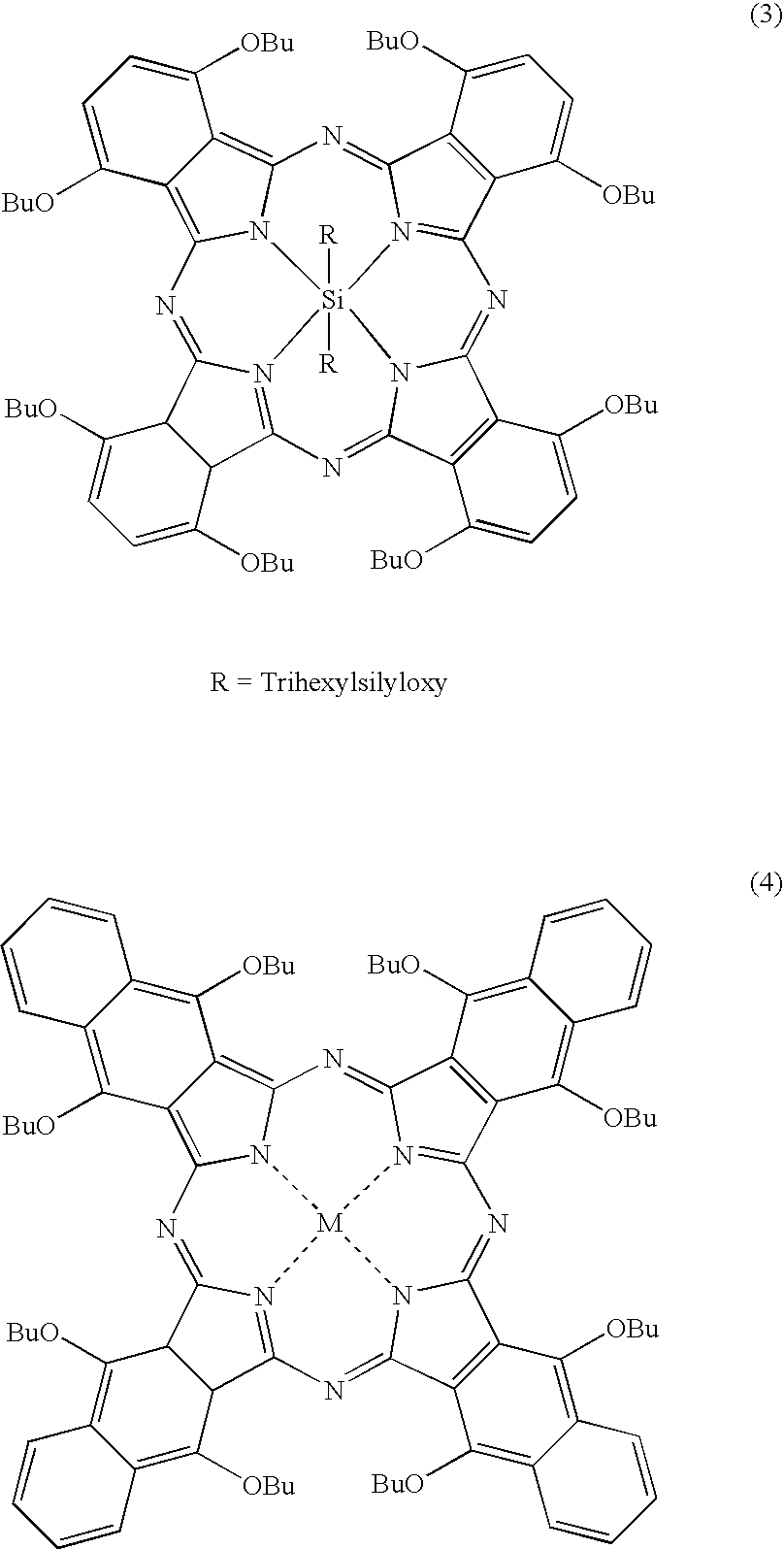
In accordance with the embodiments illustrated in FIG. 1, 2 grams of dibenzyl oxalate was heated to melting (about 85° C.). 20 grams of activator bisphenol-A and one gram of antenna silicon 2,3 naphthalocyanine bis(trihexylsilyloxide) (Formula 1), were dissolved in the melted dibenzyl oxalate. The activator / antenna solution 20 was cooled and ground into a fine powder 70.

Five grams of the ground activator / antenna powder 70 was dissolved in 15.3 g Nor-Cote CDGOOO UV-lacquer 30 to form the lacquer / antenna / activator solution 40.

Ten grams of m-terphenyl (accelerator) 50 was melted in a beaker. The melt 50 was heated to 110° F. 100 grams of 2′-a...

example 2

The method of Example 1 was carried out, except that 20 grams of phenol, 4,4′-sulfonylbis[2-(2-propenyl)-(9CI) (Formula 10):

was used as the activator and 1.2 grams of antenna silicon 2,3 naphthalocyanine bis(trihexylsilyloxide) (Formula 1), were dissolved in the melted dibenzyl oxalate to form the activator / antenna solution 20. Activator / antenna solution 20 was cooled and ground into a fine powder 70. Additionally, instead of using 100 grams of 2′-anilino-3′-methyl-6′-(dibutylamino) fluoran as the leuco-dye, 15 grams of leuco-dye 2-anilino-3-methyl-6-(N-ethyl-N-isoamylamino)fluorane (Formula 11) (average particle size <5 μm) were used to form the accelerator / leuco-dye solution.

As with Example 1, the mixture of leuco-dye / antenna / accelerator alloy and lacquer / antenna / activator solution 40 was formed into a UV-curable paste 90 and screen printed onto a substrate at a thickness of approximately 7 μm to form an imaging medium. The coating on the medium was then UV cured by me...


PUM

PropertyMeasurementUnit
compositionaaaaaaaaaa
coloraaaaaaaaaa
frequencyaaaaaaaaaa

Abstract

A composition, method, and system for recording an image. The system includes an imaging material in which radiation energy is absorbed by an antenna material. The antenna material may be chosen from the group consisting of phthalocyanines and naphthalocyanines.

Description

BACKGROUND Materials that produce color change upon stimulation with energy (e.g., light or heat) may have possible applications in imaging. For example, such materials may be found in thermal printing papers and instant imaging films. Generally, the materials and compositions known so far may require a multifilm structure and further processing to produce an image (e.g., instant camera films). And in the case of facsimile and thermal head media, high energy input of greater than 1-5 J / cm2 is needed to achieve good images. The compositions in multifilm media may require control of diffusion of color-forming chemistry and further processing, and are in separate phases and layers. Many thermal and facsimile paper coatings consist of coatings prepared by applying fine dispersions of more than two components. The components mix and react upon application of energy, resulting in a colored material. For the necessary mixing, the particles may need to contact across three or more phases o...

Claims


Application Information

Patent Timeline
Patent Type & Authority Applications(United States)
IPC IPC(8): B41M5/30B41M5/337G11B23/40
CPCB41M5/30B41M5/3375Y10S430/165Y10S430/146G11B23/40G03C1/053G03C1/49845G03C1/833
Inventor GORE, MAKARAND P.
Owner HEWLETT PACKARD DEV CO LP
Why Eureka
Try Eureka