Gas sensor
a technology of gas sensors and sensors, applied in the field of gas sensors, can solve the problems of prolonging the life of the elements and prolonging the life of the gas sensors, and achieve the effect of preventing sensitivity lowering
- Summary
- Abstract
- Description
- Claims
- Application Information
AI Technical Summary
Benefits of technology
Problems solved by technology
Method used
Image
Examples
first embodiment
[0042] Now details of this invention will be described by reference to the illustrated embodiments.
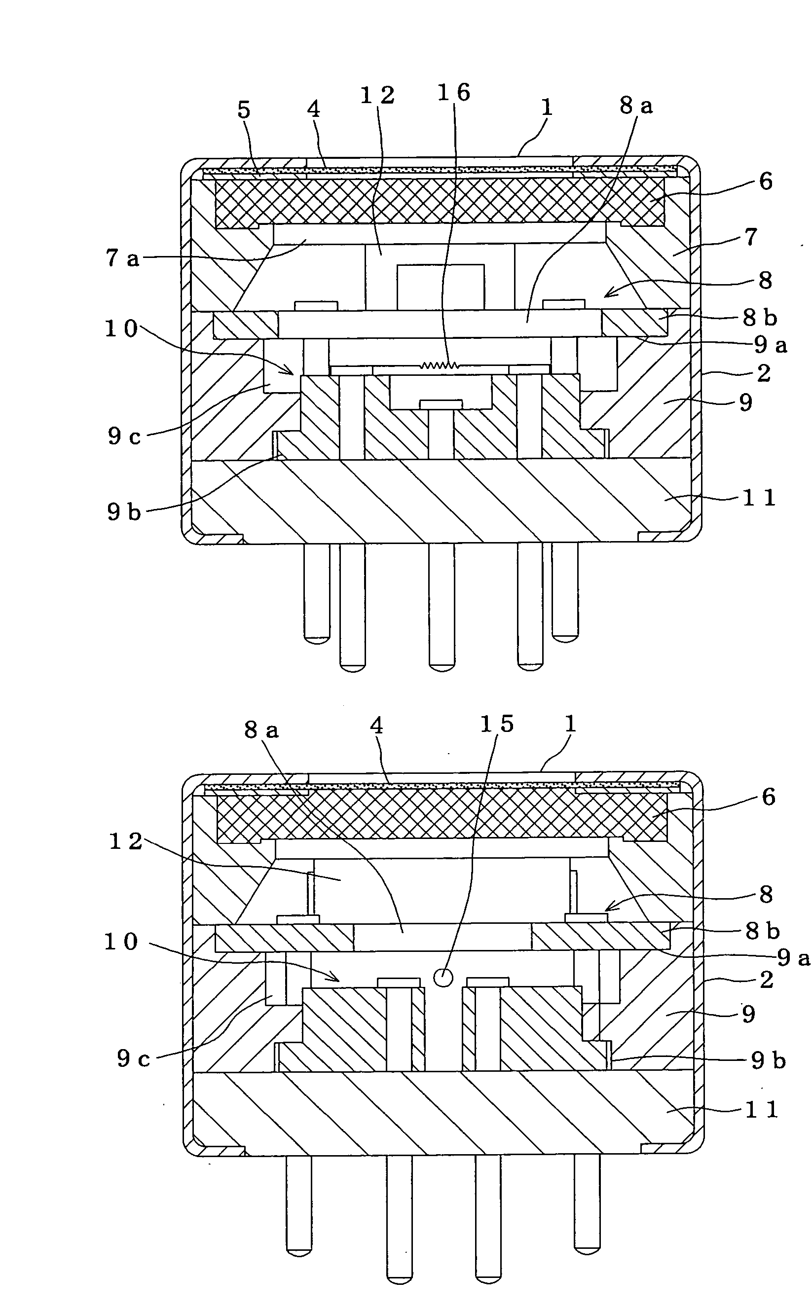
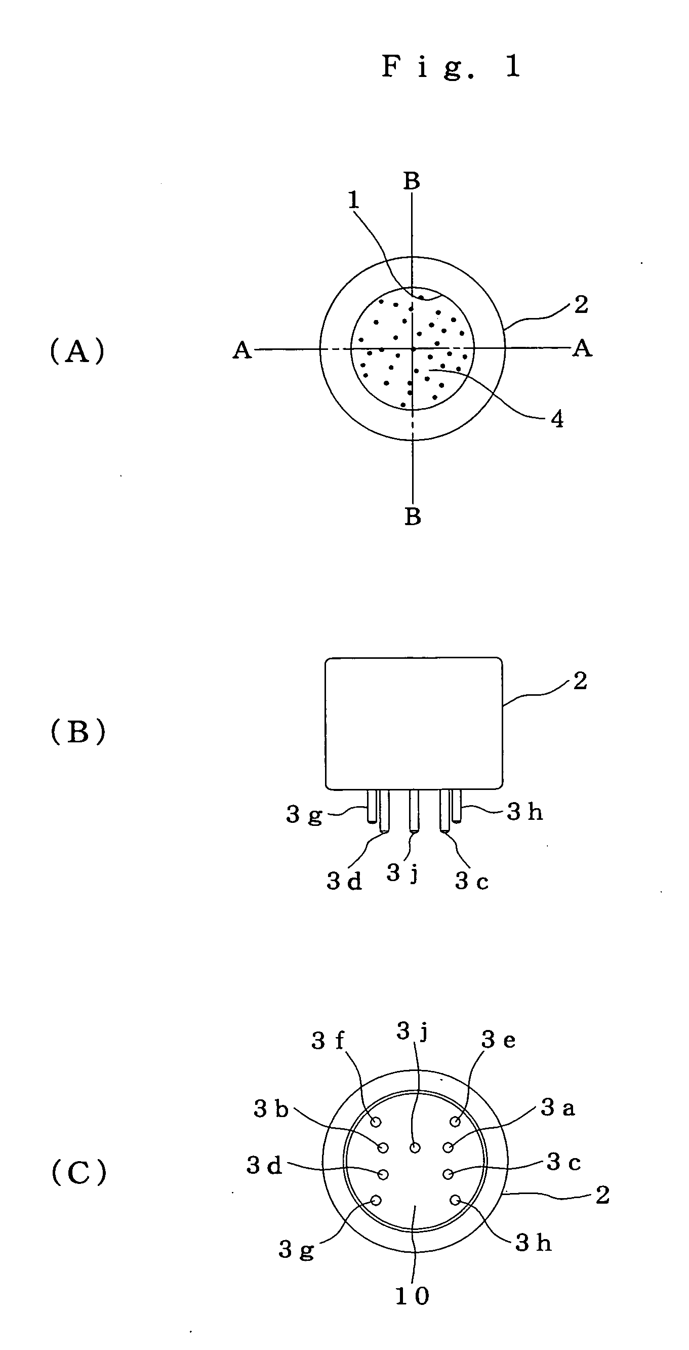
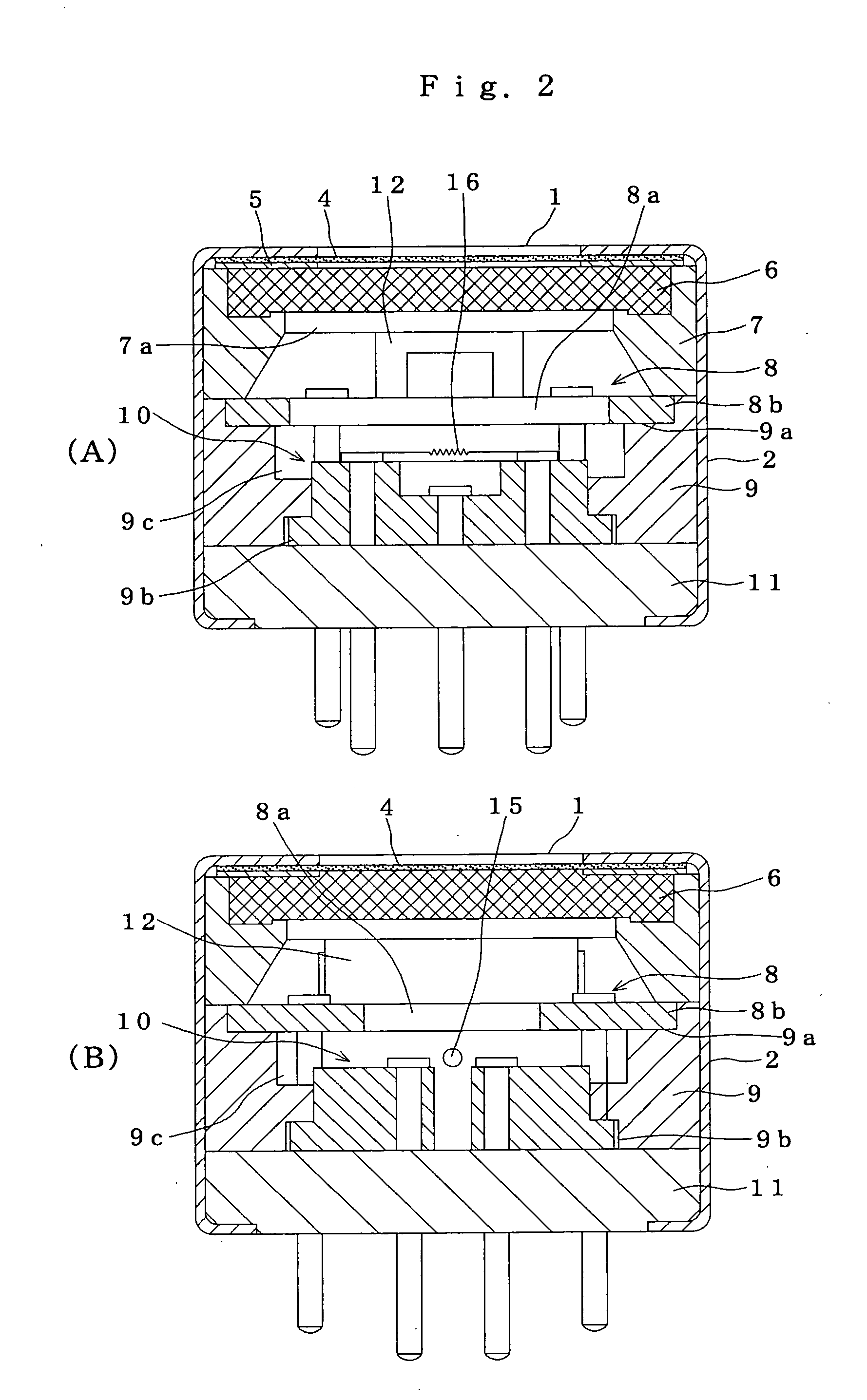
[0043]FIGS. 1 and 2 show a first embodiment of the gas sensor according to this invention. A case 2 has a specimen gas intake 1 at one end thereof and lead pins 3a to 3h for connection at the other end thereof. The case 2 holds a water-repelling filter 4, a packing 5, a sintered porous metal sheet 6, a first spacer 7, a heating unit 8, a second spacer 9, a gas-sensing unit 10, and a base plate 11 stacked in that order from the side of the specimen gas intake 1. The other end of the case 2 is constricted and fastened so that the connection lead pins 3a to 3h and a positioning pin 3j from the gas-sensing unit 10 are pulled out.
[0044] The water-repelling filter 4 is made of a porous Teflon (registered trade mark) resin that prevents the ingress of liquid and dust. The sintered porous metal sheet 6 is made by sintering metal particles into a porous sheet.
[0045] The first spacer 7 suppor...
fifth embodiment
of the Heater
[0088] In the embodiment shown in FIGS. 15(A) to (C), paired heaters 46D lying along the surface of the base 38 are disposed on the outside of the sensing element39 and temperature-compensating element 40. That is, the sensing element 39 and temperature-compensating element 40 are disposed between the paired heaters 46D at equal distance there from. The two rectangular heaters 46D, with the heat-release surfaces 49D thereof facing toward the specimen gas intake 35, heat the gas-sensing chamber 34. Reference numeral 48D denotes the leadwire of the heater 46D.
[0089] This embodiment also prolongs the life of the sensing element 39 by directly heating the inside of the gas-sensing chamber 34 with the heaters 46D in the same manner as the above-described embodiments. In particular, the heaters 46D that can be mounted on the base together with the sensing element 39 and temperature-compensating element 40 facilitate the supporting of the heaters 46D and manufacturing of the ...
second embodiment
of the Specimen Gas Intake
[0094] In a hydrogen sensor 25 shown in FIG. 16, the sintered porous metal sheet 43 and the water-repelling filter 44 of, for example, polytetrafluoroethylene are fitted to the specimen gas intake 35 from within the gas-sensing chamber 34 in such a manner as to close the intake. The sintered porous metal sheet 43 and water-repelling filter 44 are fitted from within the flange 33. The water-repelling filter 44 having a thickness of 150 μm to 300 μm blocks the passage of water droplets while permitting the passage of water vapor.
[0095] This embodiment is characterized in that the specimen gas intake 35 protrudes to the inside of the exit passage 24. That is, the cylindrical segment 32 and cylindrical wall 45 are formed so that the specimen gas intake 35 inclines downward toward the downstream of the flow (indicated by the arrow A) of the off-gas in the exit passage 24.
[0096] The sintered porous metal sheet 43 and water-repelling filter 44 fitted to the spec...
PUM
 Abstract
Description
Claims
Application Information
 - R&D
- Intellectual Property
- Life Sciences
- Materials
- Tech Scout
- Unparalleled Data Quality
- Higher Quality Content
- 60% Fewer Hallucinations
Browse by: Latest US Patents, China's latest patents, Technical Efficacy Thesaurus, Application Domain, Technology Topic, Popular Technical Reports.
© 2025 PatSnap. All rights reserved.Legal|Privacy policy|Modern Slavery Act Transparency Statement|Sitemap|About US| Contact US: help@patsnap.com


