Image forming apparatus
a technology of image bearing parts and forming apparatuses, applied in electrographic process apparatus, instruments, optics, etc., can solve the problem of somehow requiring cleaning, and achieve the effect of reducing image density, improving stability of surface potential of image bearing parts, and preventing sensitivity deterioration
- Summary
- Abstract
- Description
- Claims
- Application Information
AI Technical Summary
Benefits of technology
Problems solved by technology
Method used
Image
Examples
first embodiment
[0054]In the following, with reference to the attached drawings, a first embodiment of the present invention will be described in detail.
[0055](1-1) Description of Overall Schematic Configuration of Image Forming Apparatus
[0056]In FIG. 2, an image forming apparatus 1 is an intermediate transfer in-line type laser beam printer employing an electrophotographic process. FIG. 7 is a wiring diagram of an application system of a charging bias, a developing bias, a primary transfer bias, and a secondary transfer bias of the image forming apparatus 1. Referring to FIGS. 2 and 7, an overall schematic configuration of the image forming apparatus 1 according to the embodiment will be described.
[0057]The image forming apparatus 1 forms an image corresponding to image data (electrical image information) input from a printer controller 200 connected via an interface 201 to a printer control portion 100 onto a recording material (sheet, transfer material) P serving as a recording medium, and outpu...
embodiments
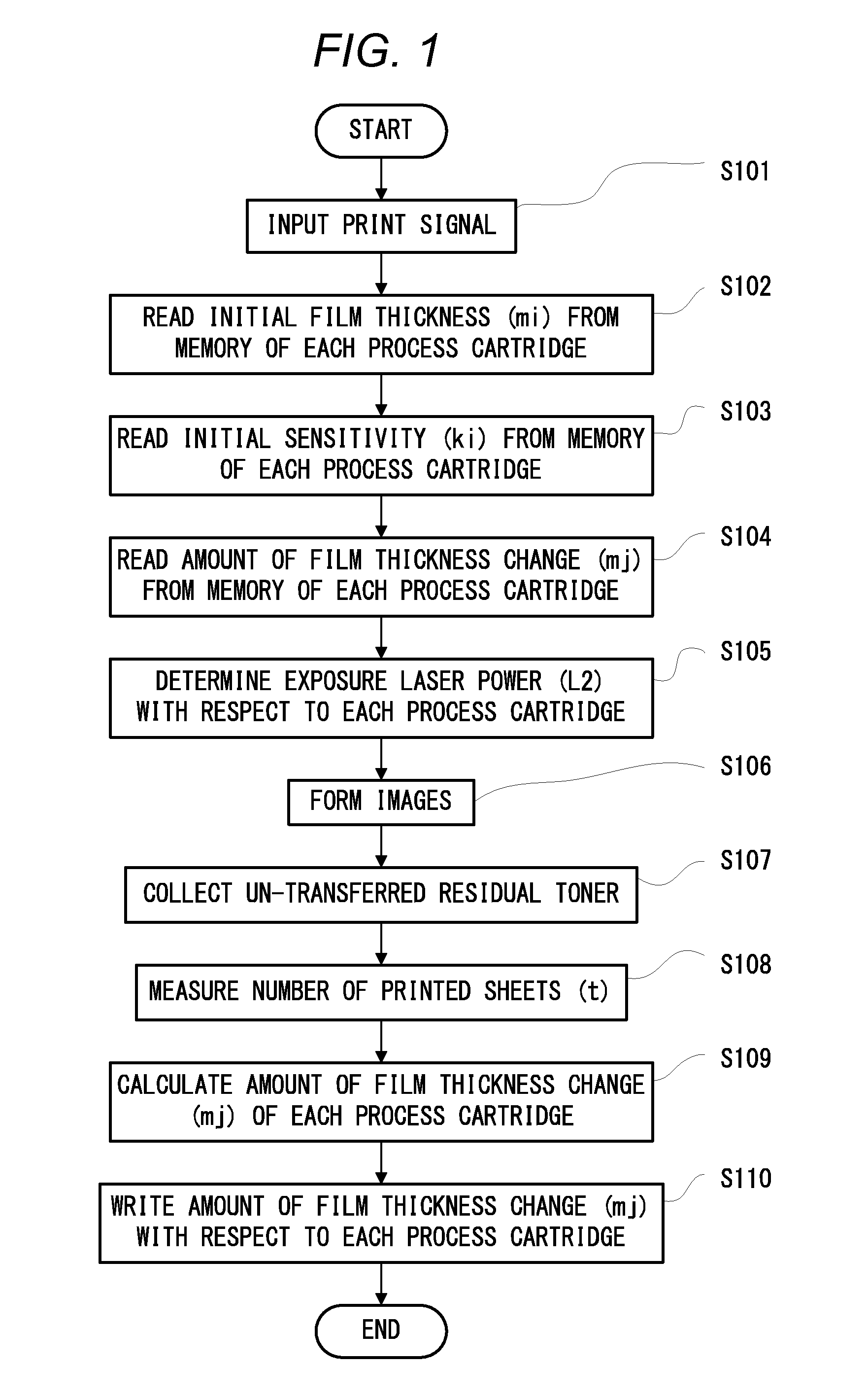
[0104]In view of this, in embodiments of the present invention, for the purpose of preventing sensitivity deterioration of the drum 11, the exposure amount for the photosensitive drum is kept low during formation of the “reverse transfer electric field” when the un-transferred residual toner collecting operation (developer collecting operation) is executed. Further, the exposure amount is controlled based on the information of use of the drum 11.
[0105]That is, the control portion 100 controls the exposure power of the laser exposure unit (exposure device) 20 in order to obtain a predetermined potential difference between the drum 11 and the primary transfer roller 31 based on the information stored in the memory 17.
[0106]Referring to FIGS. 3, 4A, and 4B, from the viewpoints of sequence and drum potential characteristics, a specific description will be provided of the control. In this case, in the state of the initial film thickness of 18 μm, as illustrated in FIGS. 3 and 4A, the exp...
second embodiment
[0126]The image forming apparatus 1 and the drum 11 according to a second embodiment of the present invention are similar to those of the first embodiment. In the embodiment, in accordance with the film thickness of the drum 11, the primary transfer bias applied during the un-transferred residual toner collecting operation is controlled to stabilize the “reverse transfer electric field.”
[0127](2-1) Description Relating to Un-Transferred Residual Toner Collecting Operation
[0128]In the embodiment, for the purpose of preventing sensitivity deterioration of the drum 11, the exposure amount for the drum 11 is kept low during formation of the “reverse transfer electric field” in the un-transferred residual toner collecting operation. Then, based on the information of the use of the drum 11, the primary transfer bias during applied the un-transferred residual toner collecting operation is controlled.
[0129]That is, in order to obtain a predetermined potential difference between the drum 11 ...
PUM
 Abstract
Description
Claims
Application Information
 - R&D
- Intellectual Property
- Life Sciences
- Materials
- Tech Scout
- Unparalleled Data Quality
- Higher Quality Content
- 60% Fewer Hallucinations
Browse by: Latest US Patents, China's latest patents, Technical Efficacy Thesaurus, Application Domain, Technology Topic, Popular Technical Reports.
© 2025 PatSnap. All rights reserved.Legal|Privacy policy|Modern Slavery Act Transparency Statement|Sitemap|About US| Contact US: help@patsnap.com


