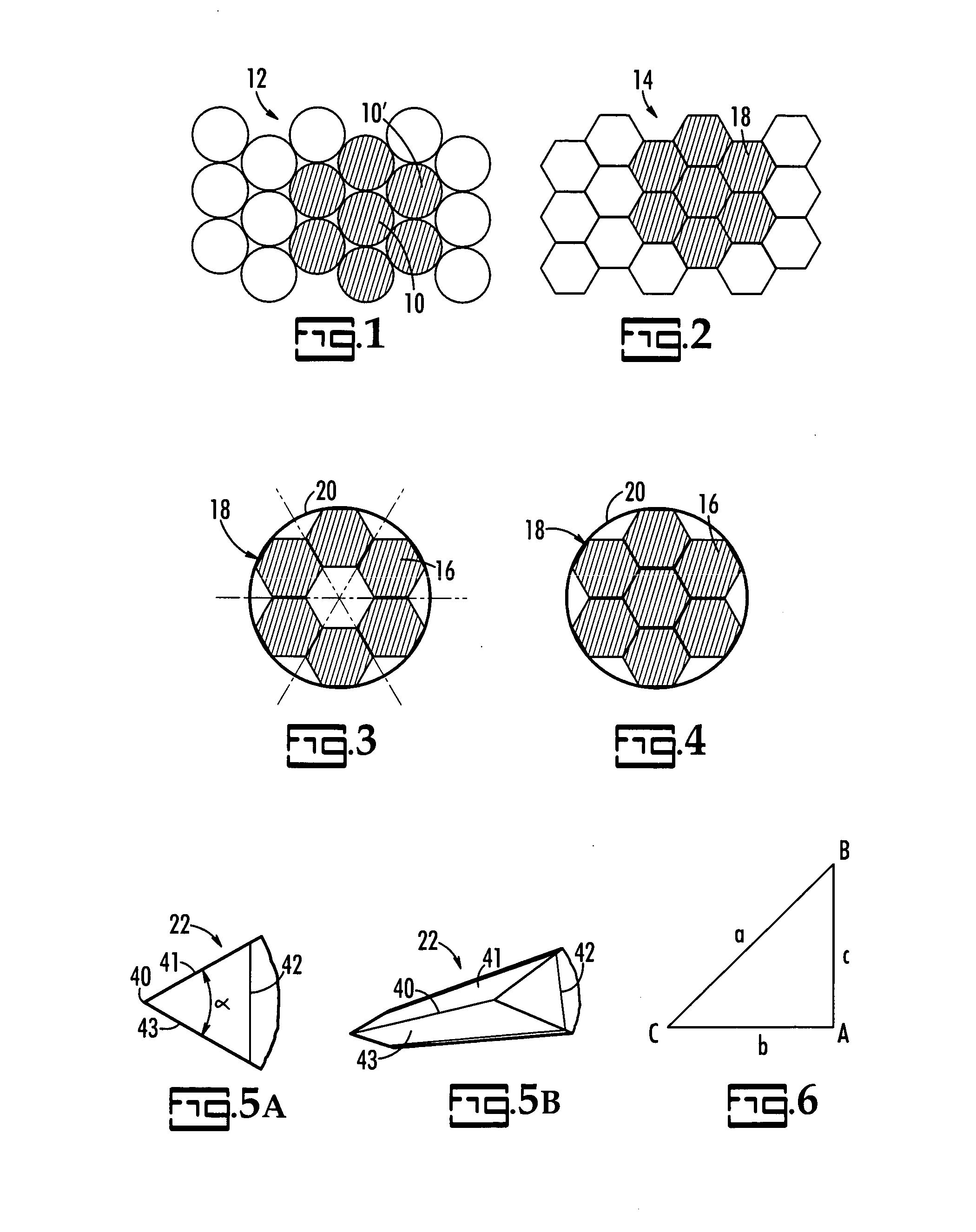
[0016] A feature of the present invention is the formation of a log piece that has an angle of approximately 60° at the interior edge of the log piece. As discussed, the pieces are formed into triangular-shaped wedges. Therefore, the cross-section of these pieces includes a triangle. Preferably, the interior edge of the log piece can be the point of an equilateral triangle having angles of 600. Accordingly, for every unit of measurement, such as one inch, that one progresses outward from the interior point (at the center of the log) toward the periphery, the section gets wider by that unit of measurement (measured across to a point on the other flat side an equal distance from the corner), which can serve as the point of an equilateral triangle. The equilateral property of the log section contributes to a highly efficient log configuration, especially if the final product is also symmetrical in cross-section. Such symmetrically sawn pieces are used for “turning stock.” As used herein, “turning stock” refers to sawn pieces of logs that are put into a wood lathe or shaper to produce shaped articles of manufacture such as chair legs, baseball bats, and similarly symmetrically shaped pieces. Furthermore, because of the configuration of the log, more of a given size of a product would be obtained from the higher quality wood near the outside of the log. Generally, this result can be attributed to the fact that the curvature of the circumference of a log is not compatible with the straightness of a saw line. Typically, the wood near the center of the log is of low quality, and suitable only for uses not requiring high-quality wood. Therefore, by
cutting the log radially into triangular-shaped sections having an interior edge with an angle of approximately 60°, the lower quality wood remains near the edge of the resulting piece and more of the higher quality wood remains near the center where the final product will be
cut. Accordingly, the present log configuration makes more efficient use of the log.
[0017] Another feature of the present invention is the use of a method of radial sawing of a log round in six triangular-shaped pieces that are approximately equivalent in size and shape. This method generally yields log pieces that can be most efficiently employed in further
processing, such as forming furniture or
sports equipment. Typically, some loss of
yield efficiency can result from the fact that not every size of a type of piece is readily salable. For example, square-shaped log pieces are typically sold in 2″, 2.5″, and 3″ sizes. The yield loss from market limitations would be mitigated, however, through the selection of various shapes. For example, a log section that would not give a good yield if shaped into a salable hexagon might be efficient for shaping into a salable square. Also, new shapes and sizes might be introduced to the market. The
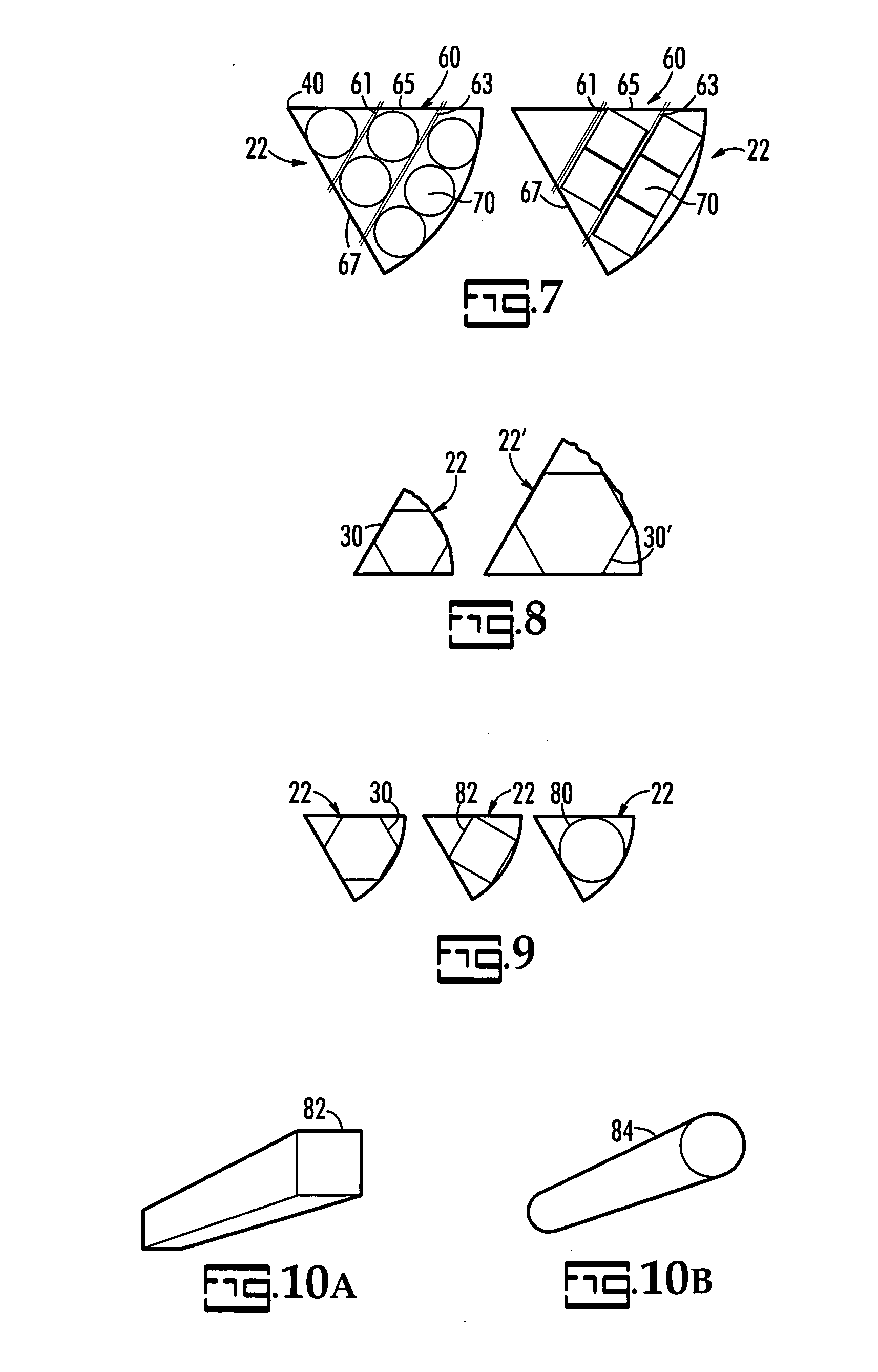
present method introduces great flexibility in log shaping and end products. The radially sawn sections of the present invention can be shaped into any number of geometric shapes, such as hexagons, octagons, rounds, and squares. Another
advantage of the
present method is flexibility as to the length of log sawn. Other methods, such as those employing tubular saws, can include a positive chucking
system, which imposes a maximum and minimum length due to considerations relating to supporting the tube when the log is shorter or longer than the tube. As used here, chucking refers to drilling a hole into the center of a log. Finally, the
present method enhances both physical and economic yield of the wood being processed. In conventional sawing, squares are sawn into a log. In such a case, a small log often cannot be sawn to produce a high physical yield, because the heart wood must be avoided, which puts a sever limitation on the sawing of symmetrical pieces. With the radial sawing method of the present invention, however, up to six
usable 2″ pieces from logs 7″ in
diameter can be produced. Additionally, the
advantage in economic yield is even better than that of physical yield. For example, in a standard 10″
diameter log, the central ⅓ of the
diameter of the log would be unusable heartwood. Through the use of the present method, the theoretical yield would be nearly 200% of the volume of salable wood from conventional sawing. Because the salable pieces from the present method would be larger, the method would yield 275% of the value derived from conventional sawing. Typically, squares and rounds of larger size sell for higher prices per
unit volume (board foot).
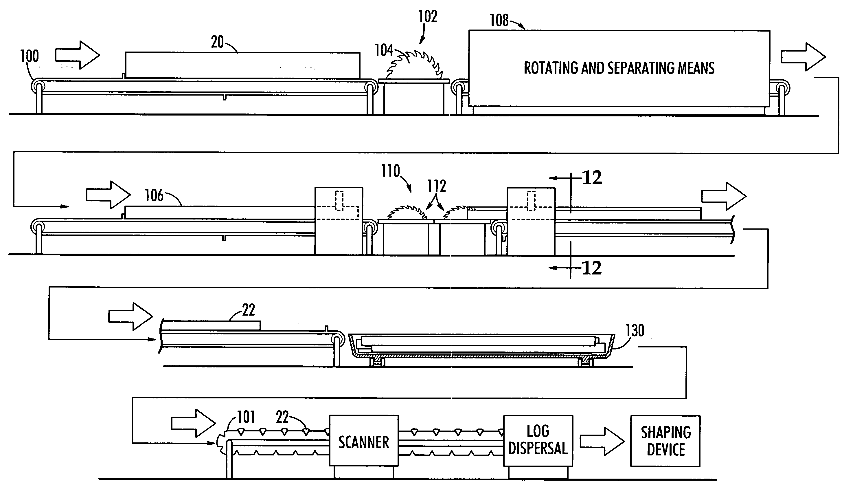
[0018] Yet another feature of the present invention is the use of a method for radial sawing including the step of forming a variety of shapes simultaneously from the triangular-shaped pieces having an interior point with an angle of approximately 60°. This feature enables both flexibility and efficiency in forming end products. The method of the present invention produces pieces that can be shaped into any number of useful articles such as hexagons, octagons, rounds, or squares. Other methods can typically only produce one type of shape in a single run. However, the present invention has the capability of producing the different shapes in a single run of the sawing
machine, as the 60° pieces can be sorted and sent through different shaping machines at one time.
[0019] Another feature of the present invention is the use of band saws. This feature saves on the overall energy and cost spent producing the final wood products, because band saws use much less energy than other types of saws, such as tube saws. Also, the equipment could be of lighter construction, because it would be subject to less stress. Finally, the use of band saws would minimize the production of
sawdust, because the band saws have a much narrower kerf than other types of saws, such as tube saws. As used herein, the term kerf refers to the pathway of a saw through wood. The kerf is reduced to
sawdust. In energy use, the radial sawing method could use band saws, which use much less energy than the tube saw. Also, the equipment could be of lighter construction, because it would be subject to much less stress. Thus, the radial method would save on both energy and capital costs, as compared to tube sawing. Further, because the standards for wood chips have gone up thereby greatly reducing the price of
sawdust, the band saws of the present method would minimize the production of this low-value byproduct.
[0020] Yet another feature of the present invention is the use of a V-groove
conveyor system for sorting the resulting triangular shaped pieces of the present sawing method before they are fed into the shaping machines. Having the pieces in a uniform position facilitates the selection scanning.


