Eureka AIR delivers breakthrough ideas for toughest innovation challenges, trusted by R&D personnel around the world.

Method and apparatus for combined cycle power plant operation

a combined cycle and power plant technology, applied in the direction of engine starters, machines/engines, turbine/propulsion engine ignition, etc., can solve the problems of significant heat generation, stress in the superheaters, and the restriction of ctg from operating at low loads for extended periods of tim

Inactive Publication Date: 2005-02-17
WASHINGTON GROUP INTERNATIONAL
View PDF9 Cites 93 Cited by
  • Summary
  • Abstract
  • Description
  • Claims
  • Application Information

AI Technical Summary

Benefits of technology

[0031] Accordingly, a general object of this invention is to provide improved apparatus and methods for controlling the operation of a combined cycle power plant during start up and part-load operations.
[0033] A specific objective of this invention is to provide a combined cycle power plant system designed to minimize thermal stress in the high pressure drum of the HRSG during startups by keeping the drum pressurized during shutdowns.
[0035] Still another specific objective of this invention is to provide a combined cycle power plant system designed to minimize startup time by economically maintaining condenser vacuum, drum pressure and header temperature during shutdowns.
[0041] A combined cycle power plant system designed and operated in accordance with this invention reduces startup emissions, thermal stress, fuel consumption and duration by modifying the design of a conventional combined cycle power plant in certain novel and unobvious ways. Methods and apparatus according to this invention comprise one or more of the following key elements:

Problems solved by technology

However, sometimes, the CTG is restricted from operating at low loads for extended periods of time because of mechanical restrictions or the desire to reduce air emissions, which are usually much higher at low loads.
Steam can actually condense in the superheater section (the part of the HRSG that increases steam temperature), causing stress in the superheaters.
Because a significant amount of energy is used to drive the compressor, a significant amount of heat is generated even at idle conditions.
Thus, when starting up, CTGs generally produce much more heat than is needed.
If a SJAE is used, sometimes the operator will take additional time to raise sufficient steam pressure to operate the SJAE.
However, once the condensation stops, the pipes heat up much more slowly.
If the temperature of the inside surface of the metal is significantly higher than that of the outside surface of the metal, the inside metal surface thermally expands more than the outside surface of the metal thereby placing the outside metal surface in tension, which can damage the metal.
Unfortunately, the CTG load level that will produce the desired steam temperature or flow will sometimes also result in extremely high levels of emissions.
Additionally, thermal stresses during startups can cause significant damage to combined cycle plants.
This sets up thermal stresses that, over time, can cause the drum to fail in fatigue.
The steam turbine cannot be heavily loaded until this change occurs, and this in turn requires that the steam turbine be carefully loaded and / or heat soaked.
Because of all of these constraints, starting up a modern combined cycle plant can require a significant amount of time and expense.
With deregulation, sales prices for electricity can vary significantly from hour to hour while fuel costs are generally constant over such a relatively short time period.
Starting during off-peak periods is expensive because the revenue earned when the electricity is sold at a low price may not recoup the fuel cost.
On the other hand, starting during on-peak periods takes time, which reduces the revenue earned during on-peak operation.
This is often difficult and expensive to do as these offsets can be in short supply.
In addition, regulators are beginning to impose restrictions on startup emissions.
None of the prior art combined cycle systems is effective in controlling emissions, in part because of the failure to operate at optimum conditions during startup.
This technique is not commonly used in recently designed combined cycle plants, however, because recent environmental regulations generally prohibit discharging CTG exhaust to the atmosphere without passing it through SCR and oxidation catalyst treatment steps.
If a bypass stack is used, it would also have to be equipped with SCR and CO catalysts, which would further increase costs.
In addition, the SCR treatment step takes enough time to operate that the bypass operation would likely be finished before the SCR was operational.
Because the HP evaporator tubes are such efficient radiators of heat, it is difficult to maintain drum pressure much above 15 psig, even if the outlet stack is provided with a damper to retain heat.
This patent does not rout exhaust gas from the start-up gas turbine to the HRSGs of the other plants, so it has the disadvantages of a plant with an auxiliary boiler.
This design, however, has the disadvantages that the cross-over duct cannot be isolated, that a small CTG is not available for startups, and that the cross-over duct (being large enough to pass the entire flow of a large CTG) imposes a large pressure drop penalty compared to a small duct required for heat-up only.
Both of the above-described fresh-air firing configurations are designed to supply steam from the HRSG in the event that the CTG trips, the CTG is unavailable, or it is uneconomic to operate the CTG.
It appears from available literature and commercial knowledge that no fresh-air firing systems have ever been designed or used to help start-up a combined cycle system.
At a minimum, it would have a smaller fan and burner because full flow and heat release is not desired during startup.

Method used


Image

  • Method and apparatus for combined cycle power plant operation
  • Method and apparatus for combined cycle power plant operation
  • Method and apparatus for combined cycle power plant operation

Examples


Embodiment Construction

[0105] A. A Representative System

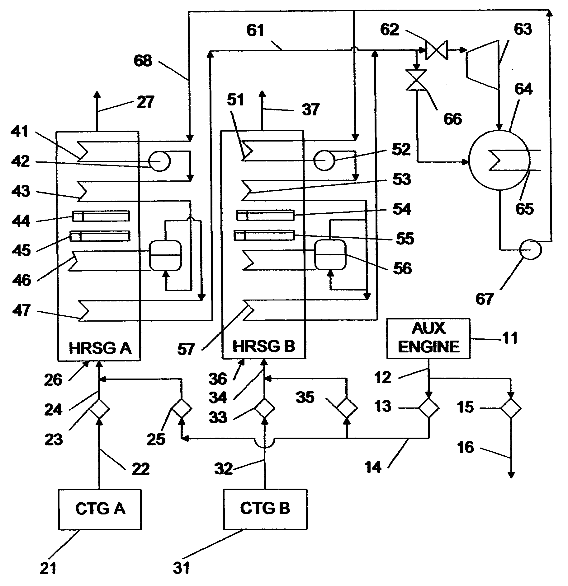
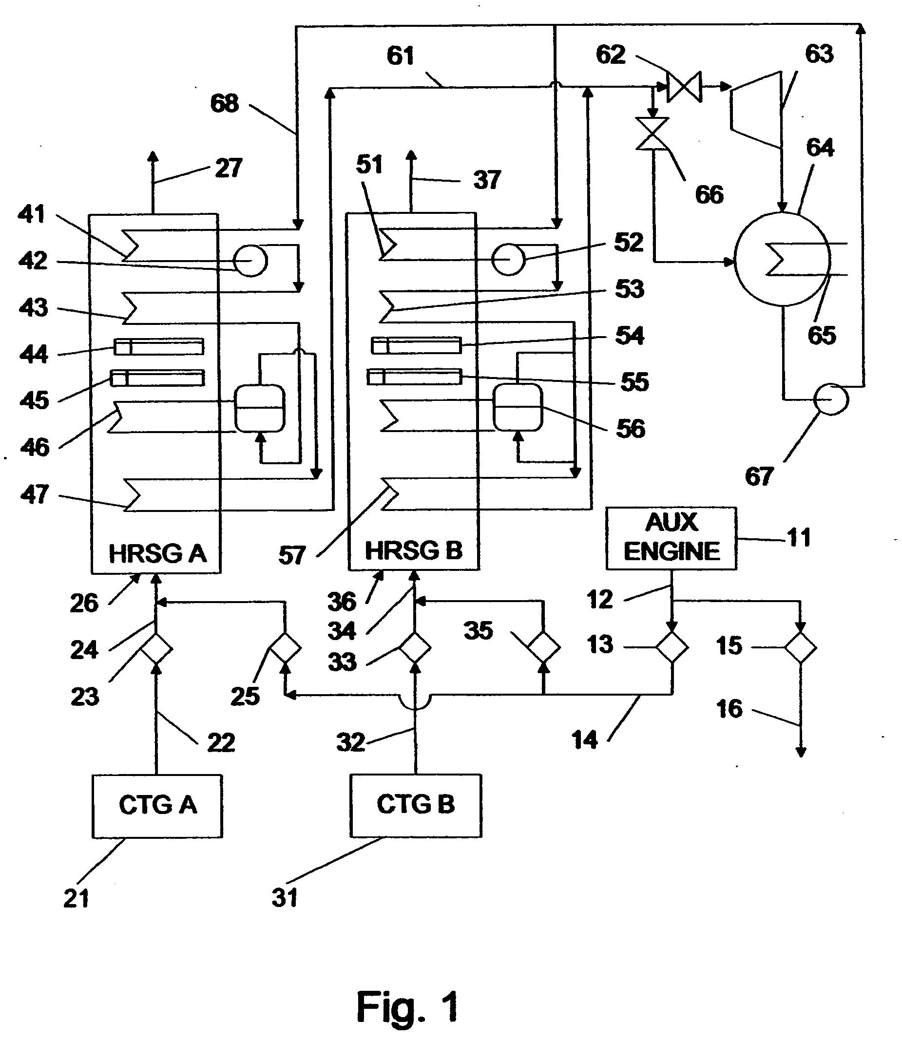
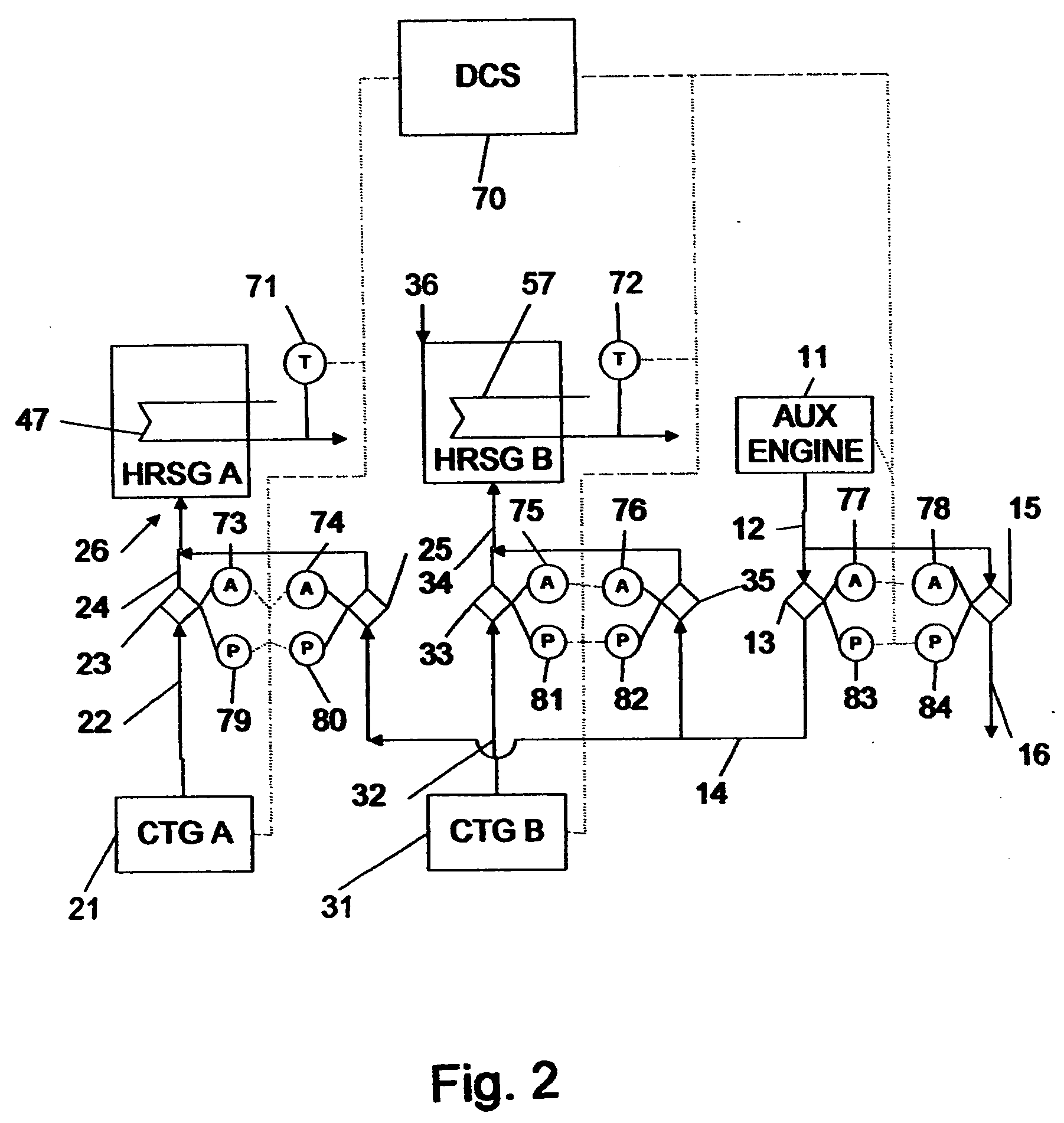
[0106] A preferred embodiment of the system of this invention is schematically illustrated in FIG. 1. In this embodiment, two CTG / HRSG trains are shown, identified respectively as trains A and B, although it will also be understood that this invention can readily be adapted to work with one, three or more such trains. For simplicity, the preferred embodiment shows a single pressure HRSG, a non-extraction-type STG, and a deaerating condenser, although more complex power plant designs can also be adapted to utilize this invention in a manner that will be appreciated by one skilled in this art. In an alternative embodiment, the HRSG can be replaced by another type of heat recovery system.

[0107] Hot gas generator or source unit 11 can be an auxiliary engine or burner, or a small gas turbine, or a diesel generator. In accordance with preferred embodiments of this invention, hot gas source unit 11 is sized so as to be capable of generating only a limited...


PUM


Abstract

Methods and apparatus are disclosed for starting up a combined cycle plant using a startup duct to connect an auxiliary engine to the inlet of a plurality of HRSGs or other heat recovery systems. Each HRSG is fed by a combustion turbine. Dampers are supplied to isolate each HRSG from the startup duct and its CTG. The auxiliary engine is also ported to a stack allowing simple cycle operation. Dampers are also supplied to isolate the auxiliary engine from the startup duct and from its stack. During startups, the large CTGs will be isolated and the auxiliary engine will be connected to the HRSGs and started, allowing the HRSG to pressurize. As each HRSG pressurizes, it is isolated from the startup duct and connected to its respective CTG. The CTG is then started and loaded. The auxiliary engine is turned off and isolated when the last HRSG pressurizes.

Description

FIELD OF THE INVENTION [0001] This invention relates generally to power plants and more particularly to methods and apparatus for controlling the operation of a combined cycle power plant during startup and part-load operations so as to minimize emissions, fuel consumption, thermal stresses and startup or load change duration and to realize other capital cost and operational savings. BACKGROUND OF THE INVENTION [0002] Until recently, most combined cycle power plants were optimized solely for base load conditions. Little thought was paid to start-up operations because it was expected that, during the early years of a power plant's life, the combined cycle plant would be operated continuously because it was more efficient than older power plants. [0003] Because start-up operation under this assumption was a small percentage of overall plant operation, inefficiencies, emissions, fuel consumption, thermal stresses, and other aspects of start-up and reduced-load operations were not consi...

Claims


Application Information

Patent Timeline
Patent Type & Authority Applications(United States)
IPC IPC(8): F02C6/18
CPCF01K13/02F01K23/10Y02E20/16F05B2260/85F05B2220/704
Inventor RADOVICH, MICHAEL J.
Owner WASHINGTON GROUP INTERNATIONAL
Why Eureka
Eureka Blog
Learn More