Exposure apparatus
- Summary
- Abstract
- Description
- Claims
- Application Information
AI Technical Summary
Benefits of technology
Problems solved by technology
Method used
Image

Examples
first embodiment
[0065] (First Embodiment)
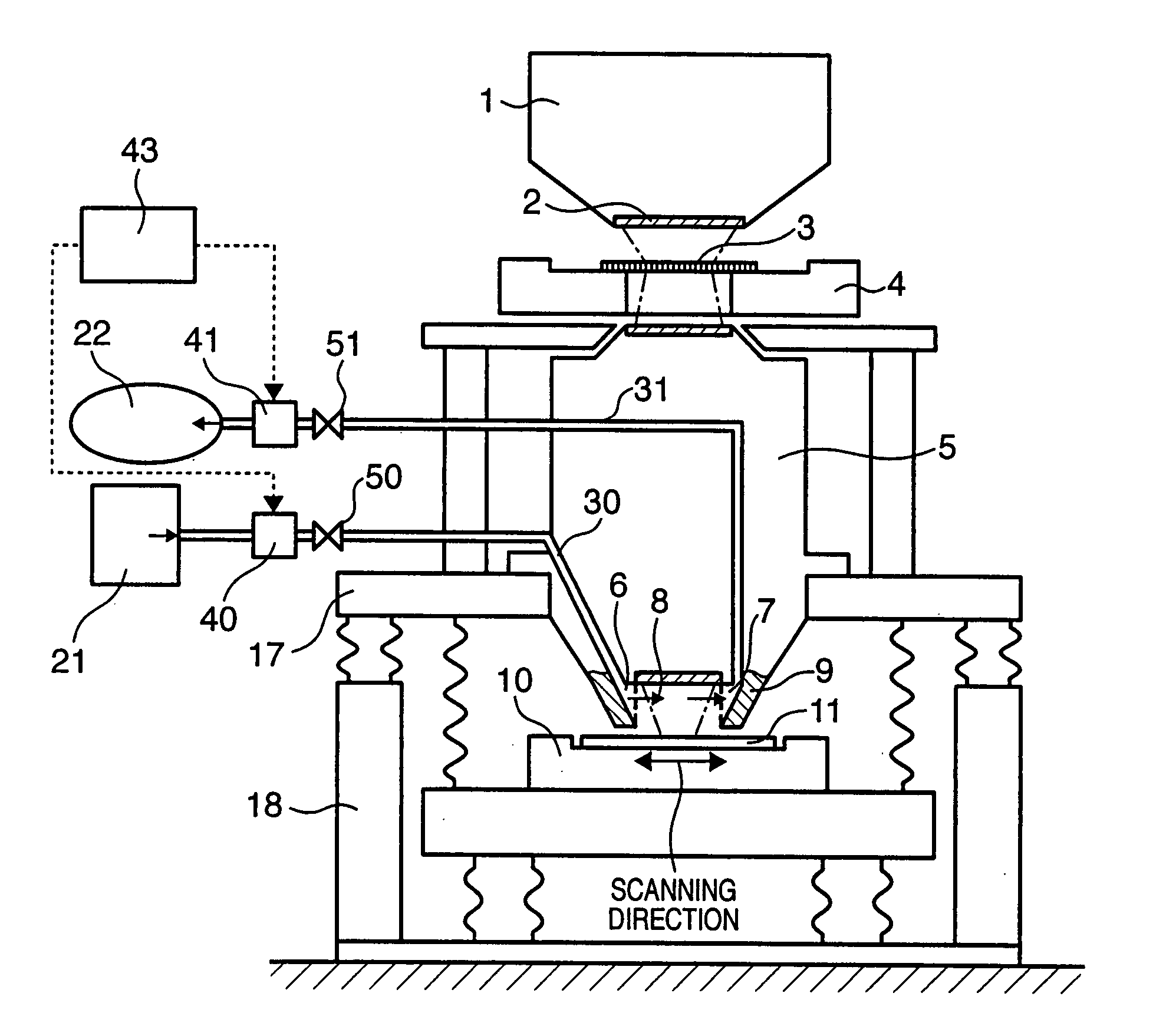
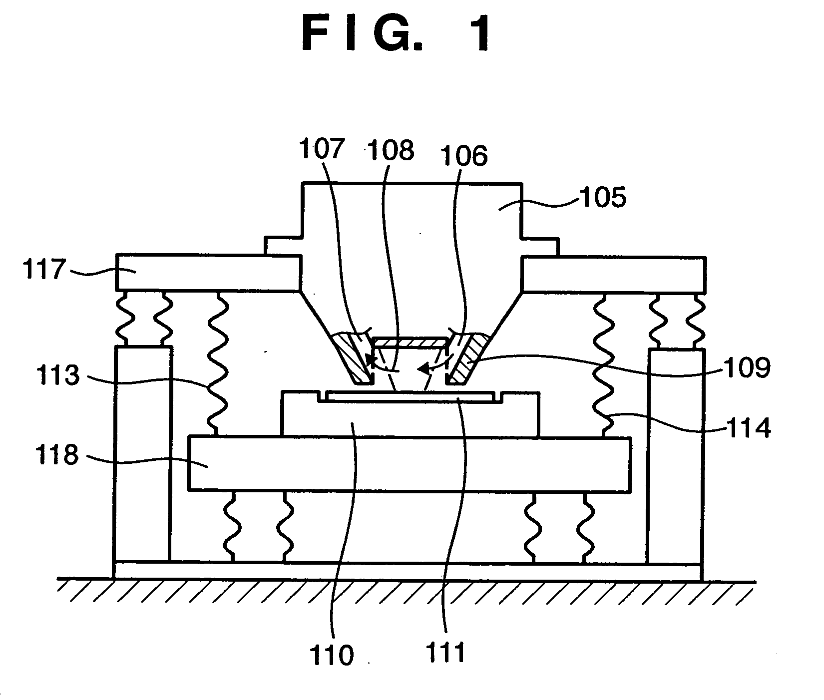
[0066]FIG. 11 is a schematic diagram showing the main part of a step & scan type projection exposure apparatus according to the first embodiment.
[0067] Referring to FIG. 11, a reticle 3 placed on a reticle stage 4 is irradiated with ultraviolet light guided from an ultraviolet light source (not shown) to an illumination system 1 in the exposure apparatus. The pattern on the irradiated reticle 3 is reduced by a projection optical system 5 and forms an image on a wafer 11 placed on a wafer stage 10. The wafer 11 is coated with a photosensitive agent, and the pattern is transferred to the wafer 11 by reduction and image formation. A cover 9 extends from the wafer-side end of the projection optical system 5 toward the vicinity of the wafer stage 10 to surround the ultraviolet light. A supply port 6 through which purge gas flows out is formed in one side of the cover 9, and a recovery port 7 through which the purge gas is drawn by suction is formed in the other ...
second embodiment
[0080] (Second Embodiment)
[0081] In the second embodiment, the influence of the gas, supplied from the outside of the cover 9, on purging is decreased.
[0082]FIG. 12 is a diagram for explaining the schematic arrangement of an exposure apparatus according to the second embodiment. The second embodiment exemplifies a case wherein a cover 9 having a supply port 6 and recovery port 7 is placed in the one-directional flow (ambient flow) of air or gas having a comparatively high impurity concentration. Flow rate control of the purge gas supplied / recovered through the supply port 6 / recovery port 7 is the same as that of the first embodiment, and a description thereof will be omitted.
[0083] Referring to FIG. 12, a partition wall 14 has a blow-out port 16 through which the gas blows out toward the space in the vicinity of a wafer stage, and a partition wall 13 opposing the partition wall 14 has a suction port 15 through which the gas is drawn by suction. As the gas to be supplied through th...
third embodiment
[0093] (Third Embodiment)
[0094] In the third embodiment, in addition to the supply port 6 inside the cover 9, a sub-supply port is formed through which purge gas is so supplied as to prevent the external gas from entering.
[0095]FIG. 13 is a diagram showing the arrangement of the main part of an exposure apparatus according to the third embodiment. As shown in FIG. 13, a supply port 6 and recovery port 7 are formed inside a cover 9. A sub-supply port 12 is formed in the lower end of the cover 9. The purge gas is supplied through the sub-supply port 12 toward a wafer 11. Flow rate control of the purge gas supplied / recovered through the supply port 6 and recovery port 7 is the same as that of the first embodiment, and a description thereof will accordingly be omitted.
[0096] According to the third embodiment, the sub-supply port 12 is formed to surround the periphery of the exposure area, and the purge gas supplied through the sub-supply port 12 is inert gas with an impurity concentra...
PUM
 Abstract
Description
Claims
Application Information
 - R&D
- Intellectual Property
- Life Sciences
- Materials
- Tech Scout
- Unparalleled Data Quality
- Higher Quality Content
- 60% Fewer Hallucinations
Browse by: Latest US Patents, China's latest patents, Technical Efficacy Thesaurus, Application Domain, Technology Topic, Popular Technical Reports.
© 2025 PatSnap. All rights reserved.Legal|Privacy policy|Modern Slavery Act Transparency Statement|Sitemap|About US| Contact US: help@patsnap.com