
Mechanically-stable BJT with reduced base-collector capacitance

Active Publication Date: 2005-02-03
TELEDYNE SCI & IMAGING
View PDF2 Cites 17 Cited by
  • Summary
  • Abstract
  • Description
  • Claims
  • Application Information

AI Technical Summary

Benefits of technology

[0008] A BJT and fabrication method are described which overcome the problems noted above. Base-collector capacitance is reduced by reducing the area of the base contact which is directly over the collector, while maintaining the mechanical stability of the device.
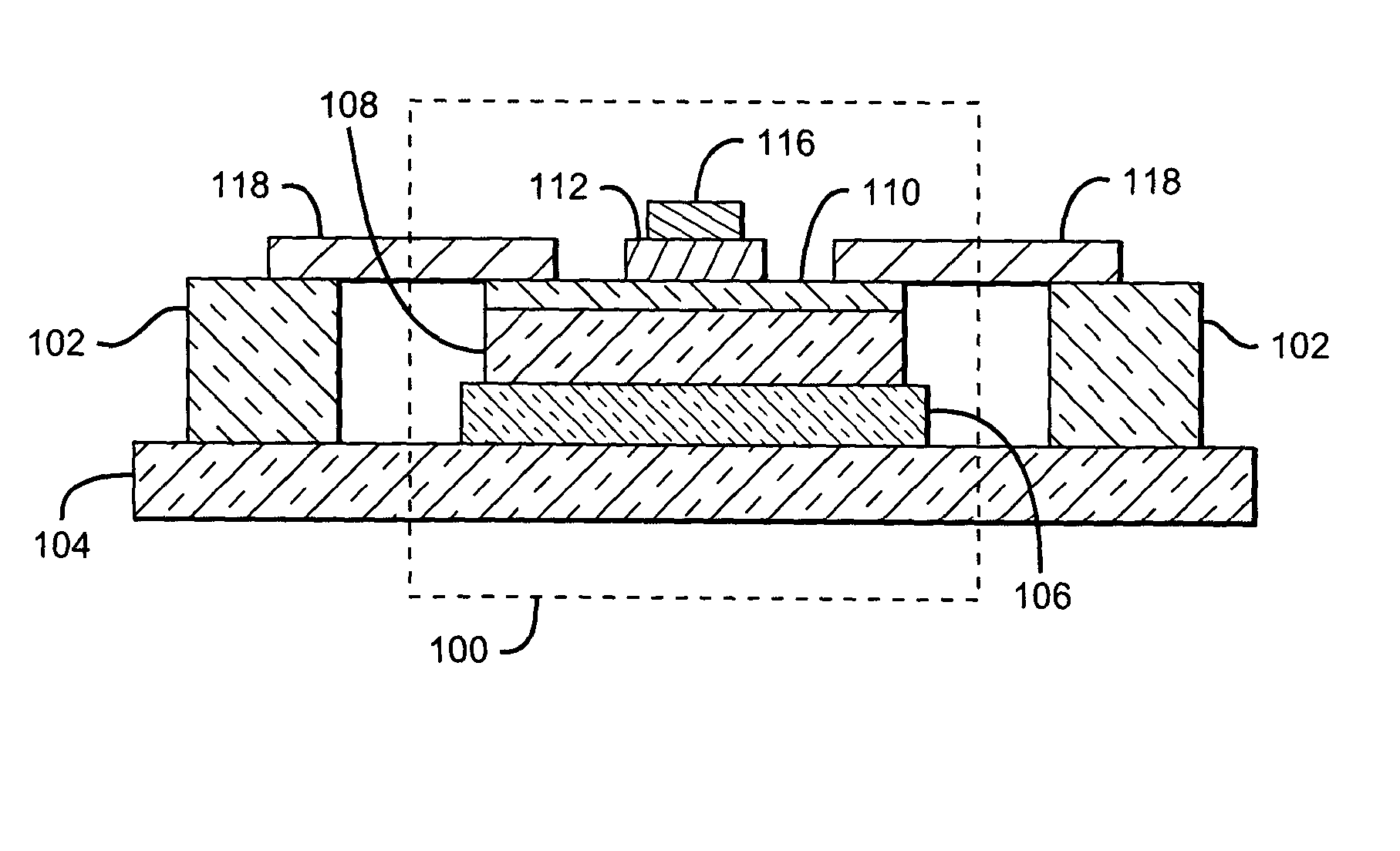
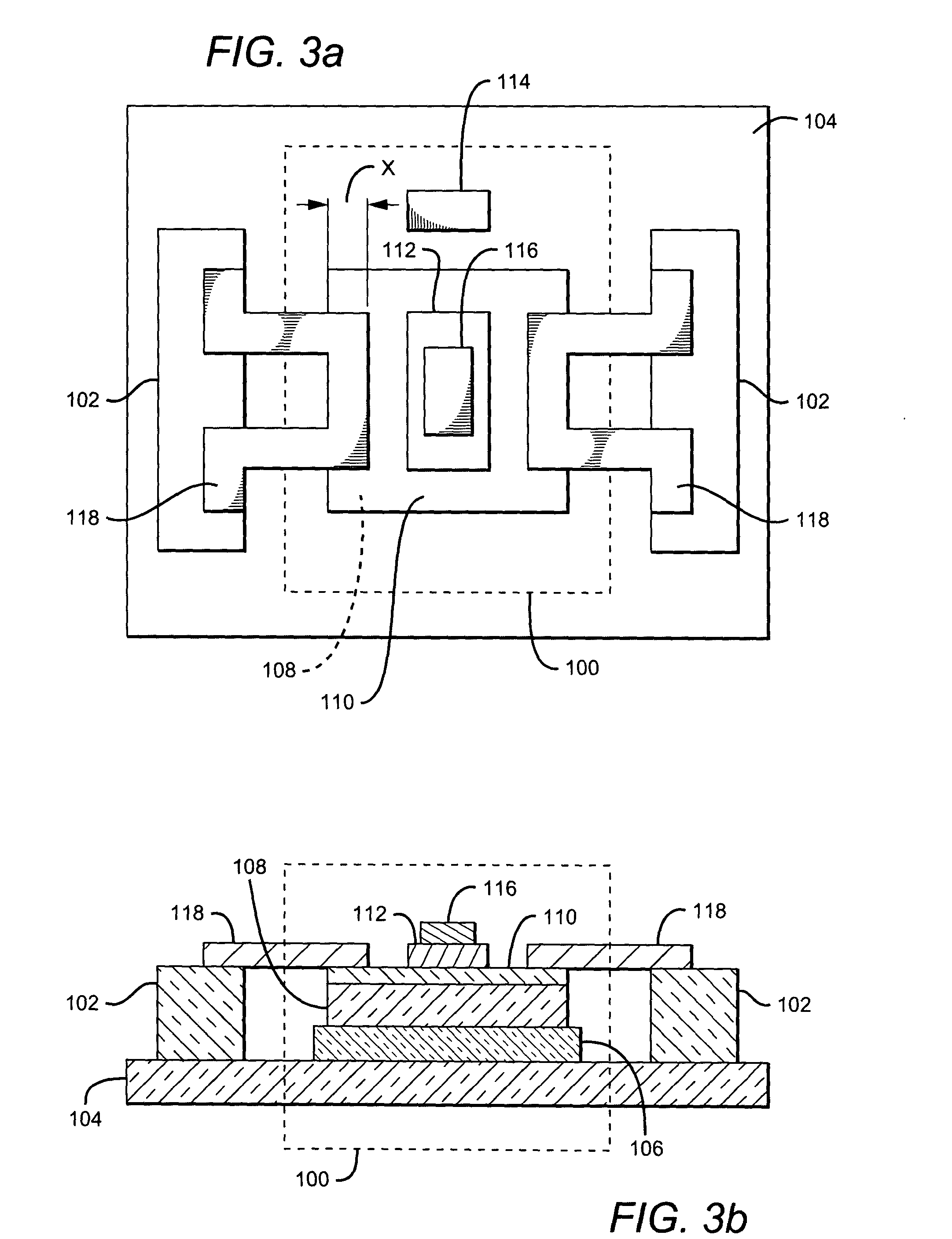
[0010] Contact to the BJT structure's base is accomplished via a metal contact which extends from the top of an adjacent support post to the edge of the base nearest the support post. The contact thus bridges the physical and electrical separation between the support post and the base and provides a base terminal for the BJT.

Problems solved by technology

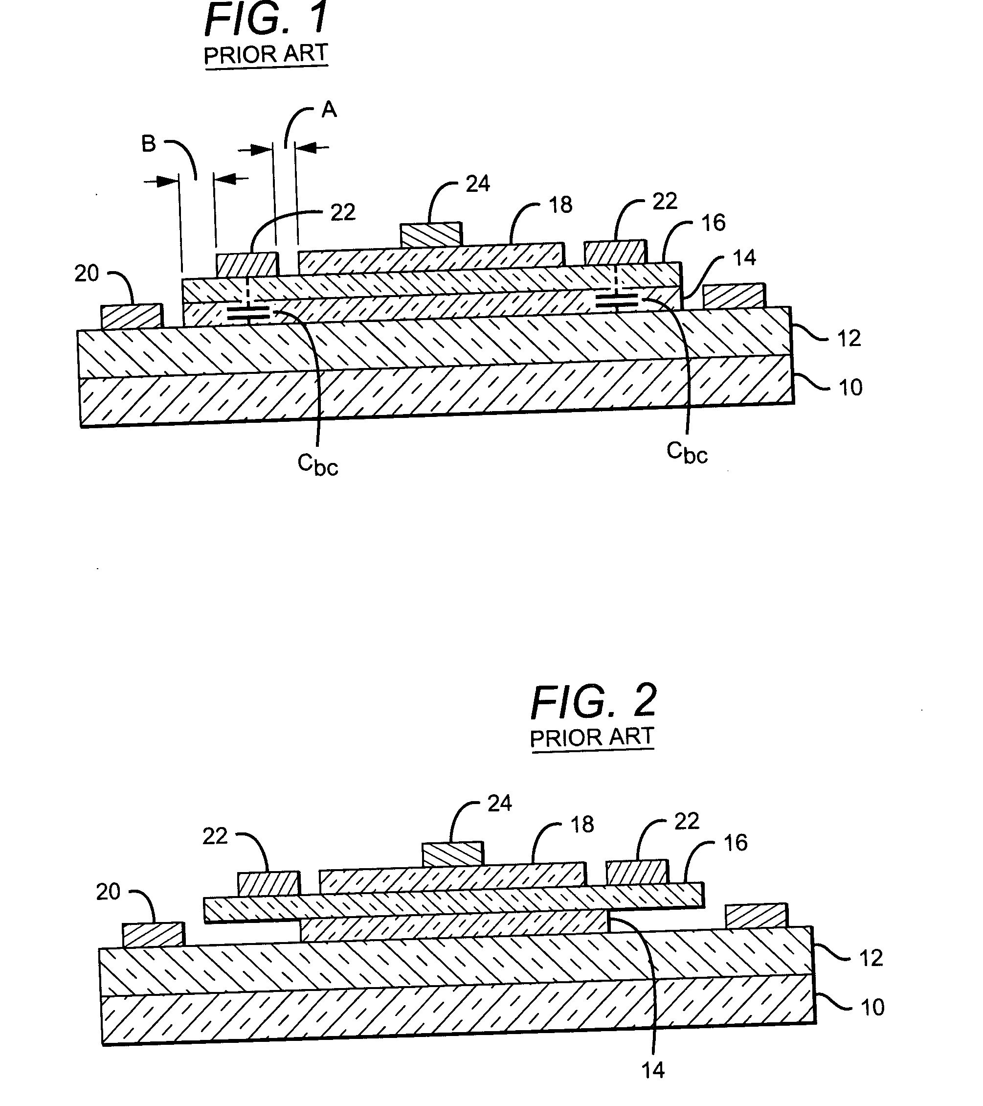
However, the undercut leaves the base and / or base contact cantilevered over the resulting empty space, leaving the overhanging edges of the base susceptible to breakage.
Subsequent processing steps may also break the base cantilever.
Such damage is likely to render the device useless.

Method used


Image

  • Mechanically-stable BJT with reduced base-collector capacitance
  • Mechanically-stable BJT with reduced base-collector capacitance
  • Mechanically-stable BJT with reduced base-collector capacitance

Examples


Embodiment Construction

[0018] An exemplary embodiment of a mechanically-stable BJT with reduced base-collector capacitance is shown in FIGS. 3a (plan view) and 3b (corresponding sectional view). The device comprises a BJT structure 100 and at least one support post 102. BJT structure 100 comprises a semi-insulating substrate 104, on top of which is formed a subcollector layer 106 (not shown in FIG. 3a for clarity). A collector layer 108 is on the subcollector, a base layer 110 is atop the collector, and an emitter 112 is formed on the base. A metal contact 114 (not visible in FIG. 3b) is formed on subcollector 106 to provide a collector terminal for the BJT, and a metal contact 116 on emitter 112 provides the device's emitter contact.

[0019] Support post 102 is formed adjacent to BJT structure 100, but is physically and electrically isolated from the BJT structure. A metal contact 118 is formed which extends from the top of the support post to the nearest edge of base 110, thereby bridging the physical an...


PUM


Abstract

A bipolar junction transistor (BJT) requires the fabrication of a BJT structure and of a support post which is adjacent to, but physically and electrically isolated from, the BJT structure. The BJT structure includes a semi-insulating substrate, a subcollector, a collector, a base, and an emitter. Metal contacts are formed on the subcollector and emitter to provide collector and emitter terminals. Contact to the structure's base is accomplished with a metal contact which extends from the top of the support post to the edge of the base nearest the support post. The contact bridges the physical and electrical separation between the support post and the base and provides a base terminal for the device. The base contact need extend over the edge of the base by no more than the transfer length associated with the fabrication process. This results in the smaller base contact area over the collector than would otherwise be necessary, and a consequent reduction in base-collector capacitance. The invention is particularly useful when forming heterojunction bipolar transistors (HBTs), built on a compound semiconductor substrate such as indium phosphide (InP).

Description

BACKGROUND OF THE INVENTION [0001] 1. Field of the Invention [0002] This invention relates to the field of bipolar junction transistor (BJT) structures, and particularly to BJT structures which reduce base-collector capacitance. [0003] 2. Description of the Related Art [0004] The RF performance of a BJT is determined by the minority carrier transit times through the base and collector, and the charging times associated with the base-emitter, base-collector, and parasitic diode junctions. Since the transit times are easily improved by thinning the base and collector layers or by changing their composition, much effort has been devoted to the reduction of the charging times. This is particularly important for devices designed for operation at very high frequencies, such as those based on compound semiconductors such as indium phosphide (InP). [0005] The charging times are determined by the capacitance present at each junction. For a compound semiconductor-based transistor, the base-em...

Claims


Application Information

Patent Timeline
IPC IPC(8): H01L23/482H01L29/423H01L29/73H01L29/732H01L29/737
CPCH01L23/4821H01L23/4822H01L29/42304H01L29/7317H01L29/732H01L2924/1305H01L29/7371H01L24/01H01L2924/00
Inventor LI, JAMES CHINGWEIPIERSON, RICHARD L. JR.BRAR, BERINDER P.S.HIGGINS, JOHN A.
Owner TELEDYNE SCI & IMAGING
Learn More