Rechargeable battery pack having a contact plate for connection to a load

Active Publication Date: 2016-06-16
ANDREAS STIHL AG & CO KG
View PDF3 Cites 0 Cited by
  • Summary
  • Abstract
  • Description
  • Claims
  • Application Information

AI Technical Summary

Benefits of technology

The patent describes a mount for a contact plate in a cell holder, which allows the contact plate to move and align itself with corresponding connection contacts, such as in a rechargeable battery shaft. This ensures a secure and mechanically loadable connection, even under high electrical loading. The mount is made of elastic contact strips that can compensate for changes in length and heat up during electrical loading. The contact plate remains displaceable, ensuring complete alignment with the connection contacts. A recess is provided in the contact strip, which acts as a fuse element, allowing the contact strip to break in a controlled manner under excessive current or voltage. This ensures safe and reliable functioning of the contact system.

Problems solved by technology

If the connection contacts and the plug-type connections do not fit one another, poor contacts may be formed.
If there are also vibrations caused by the implement, the connection contacts may lift off the plug-type connections, which can lead to increased contact wear under electrical loading.
A high power drain from the rechargeable battery pack can also lead to an increase in temperature of the individual cells and of the electrical connections, as a result of which the position of the contact plate may change.

Method used


Image

  • Rechargeable battery pack having a contact plate for connection to a load
  • Rechargeable battery pack having a contact plate for connection to a load
  • Rechargeable battery pack having a contact plate for connection to a load

Examples


Embodiment Construction

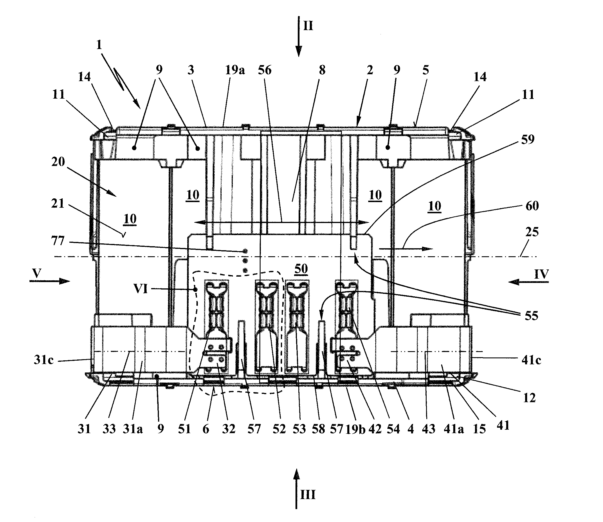
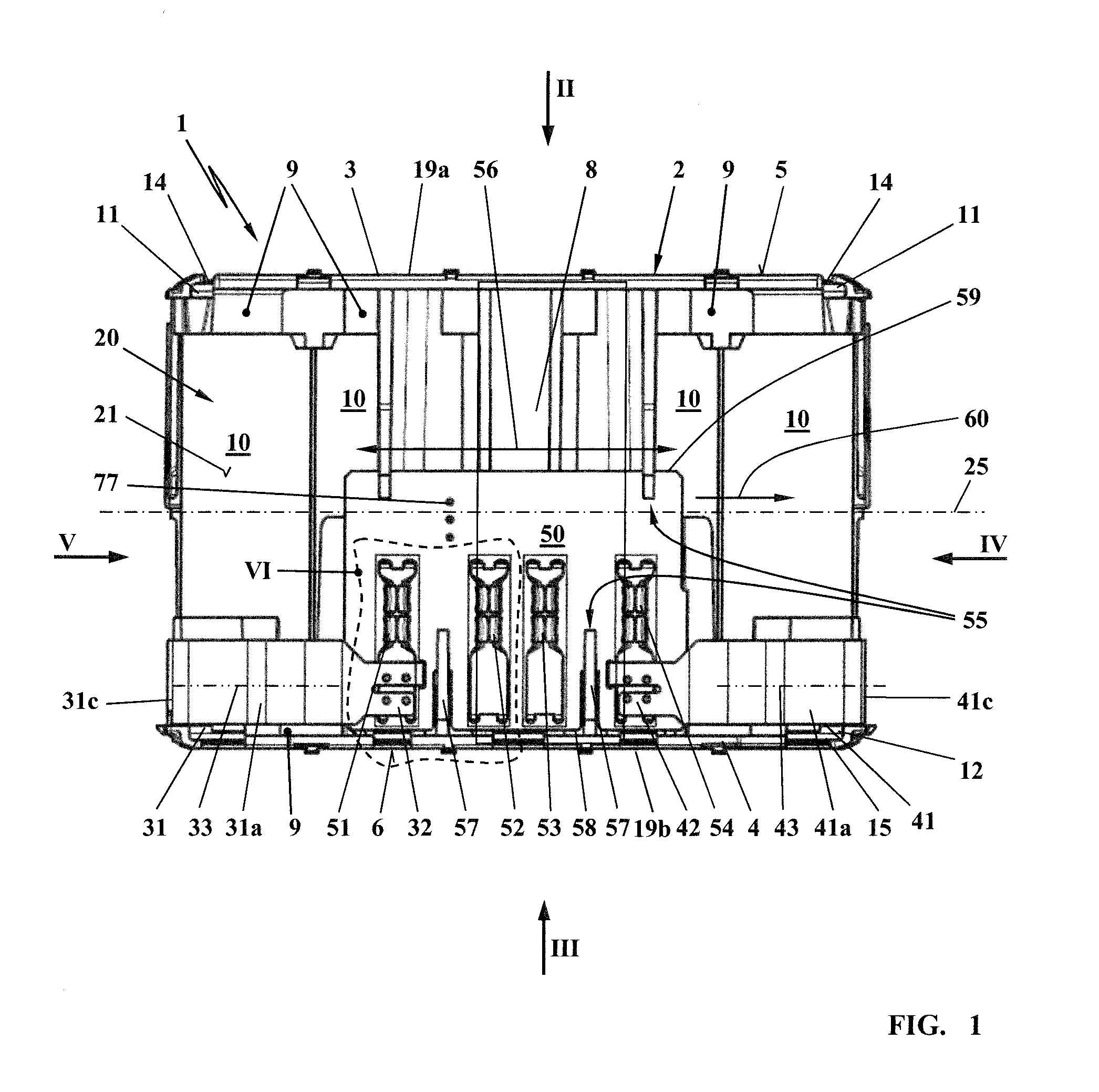
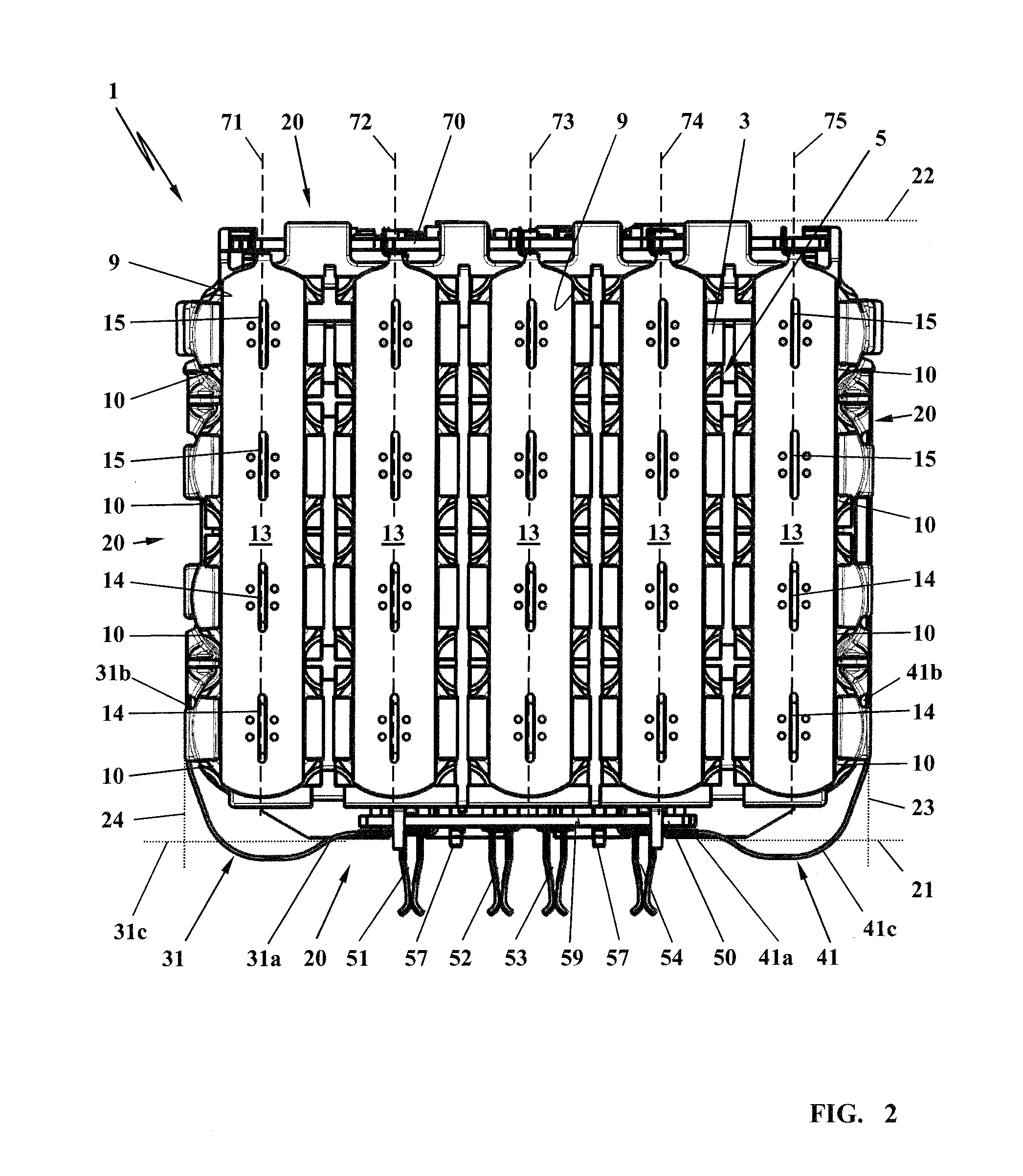
[0030]The rechargeable battery pack 1 illustrated in FIG. 1 includes a cell holder 2 and at least one individual cell 10 which as a cylindrical base shape. In this embodiment, a plurality of individual cells 10 are combined to form a rechargeable battery pack 1. In each case one end 11 of an individual cell 10 forms a positive pole 14; another end 12, lying opposite, of the individual cell 10 forms a negative pole 15. The cell holder 2 is assembled from a first, upper cell trough 3 and a second, lower cell trough 4. The first, upper cell trough 3 forms a first, upper end side 5 of the rechargeable battery pack 1. The second, lower cell trough 4 forms a second, lower end side 6 of the rechargeable battery pack 1. The ends 11 and 12 of the individual cells 10 are held in assigned receptacles 9 in the cell troughs (3, 4). The one ends 11 of the individual cells 10 lie on a common, first contact side 19a of the cell holder 2. The other ends 12 of the individual cells 10 lie on a common,...


PUM


Abstract

A rechargeable battery pack includes at least one individual cell which is accommodated in a cell holder and is in electrical contact on a contact side via a cell connector. An electric load is to be connected via a contact plate which has a plurality of plug-type connections, wherein the contact plate is located on one side face of the cell holder. In order to compensate positional tolerances between the plug-type connections of the contact plate and external connection contacts, a mount for the contact plate is provided on one side face of the cell holder, in which mount the contact plate is mounted so as to be displaceable in a displacement direction. The electrical connection between the individual cell and the contact plate is embodied by an elastic contact strip, wherein the contact strip is embodied so as to be resilient in a sprung fashion in the displacement direction of the contact plate.

Description

CROSS REFERENCE TO RELATED APPLICATION[0001]This application claims priority of German patent application no. 10 2014 018 474.9, filed Dec. 12, 2014, the entire content of which is incorporated herein by reference.BACKGROUND OF THE INVENTION[0002]Known rechargeable battery packs are usually made of an arrangement of a plurality of individual cells which are electrically connected to one another via cell connectors on one contact side in each case to form a cell assembly. The individual cells of the rechargeable battery pack are connected to an electric load via a contact plate which has a plurality of plug-type connections. The contact plate can be located on a side face of the cell holder.[0003]Rechargeable battery packs of this type are, for example, inserted into holders of electrical implements in which connection contacts are provided which are aligned in the insertion direction and engage in the plug-type connections of the contact plate. When contact is made, it is necessary ...

Claims


Application Information

Patent Timeline
IPC IPC(8): H01M2/30H01M2/34H01M2/10H01M50/528H01M50/213H01M50/264H01M50/296H01M50/503H01M50/512
CPCH01M2/30H01M2200/103H01M2/348H01M2/1016H01M50/296H01M50/503H01M50/512H01M50/264H01M50/213H01M10/425Y02E60/10H01M50/581
Inventor GAUL, HENRIKLIEBHARD, GERNOTWAGNER, DANIELSCHURR, MARTIN
Owner ANDREAS STIHL AG & CO KG
Why Eureka
Try Eureka