
Filtration system and dynamic fluid separation method

Inactive Publication Date: 2005-02-03
PHASE
View PDF99 Cites 42 Cited by
  • Summary
  • Abstract
  • Description
  • Claims
  • Application Information

AI Technical Summary

Benefits of technology

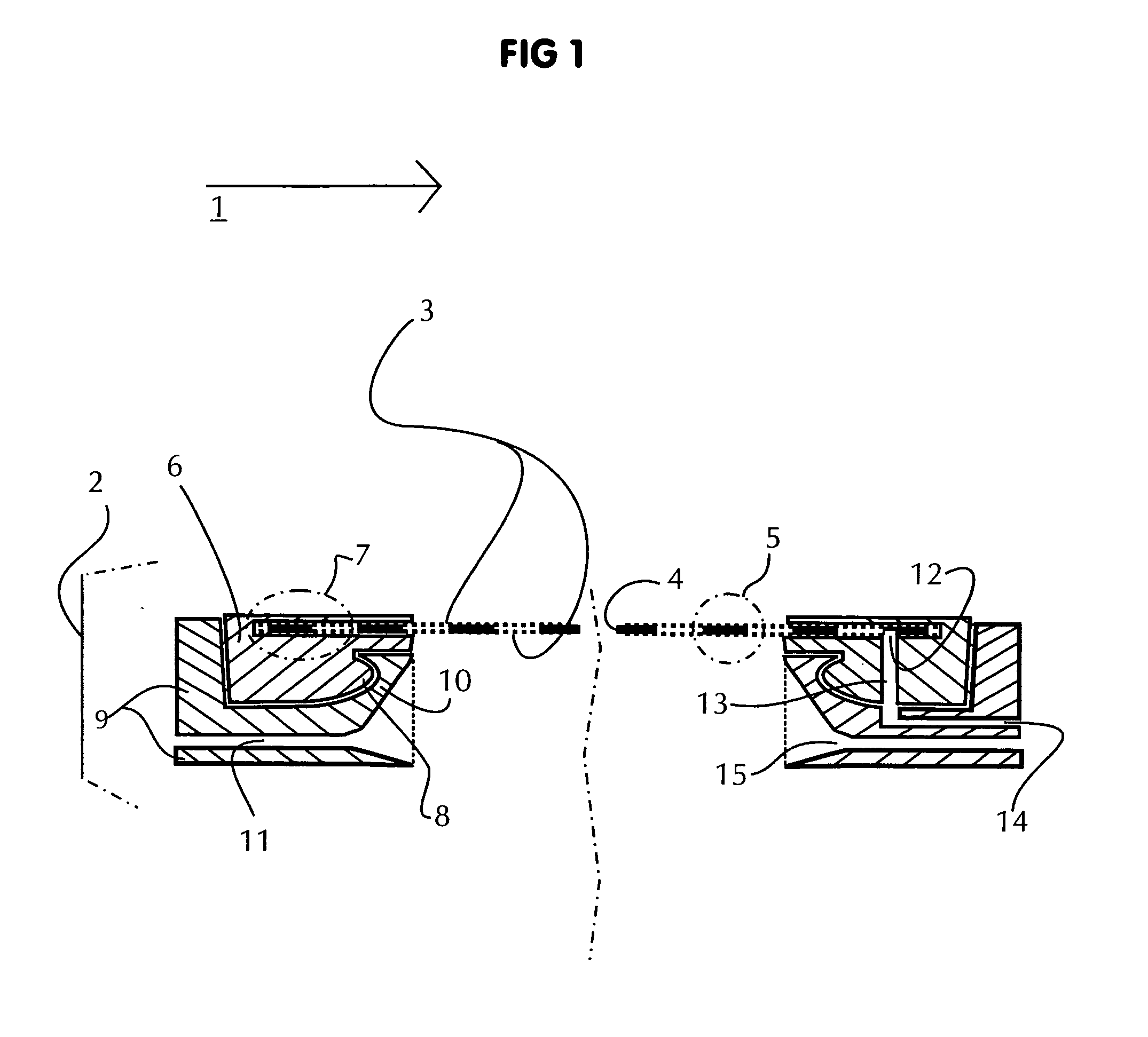
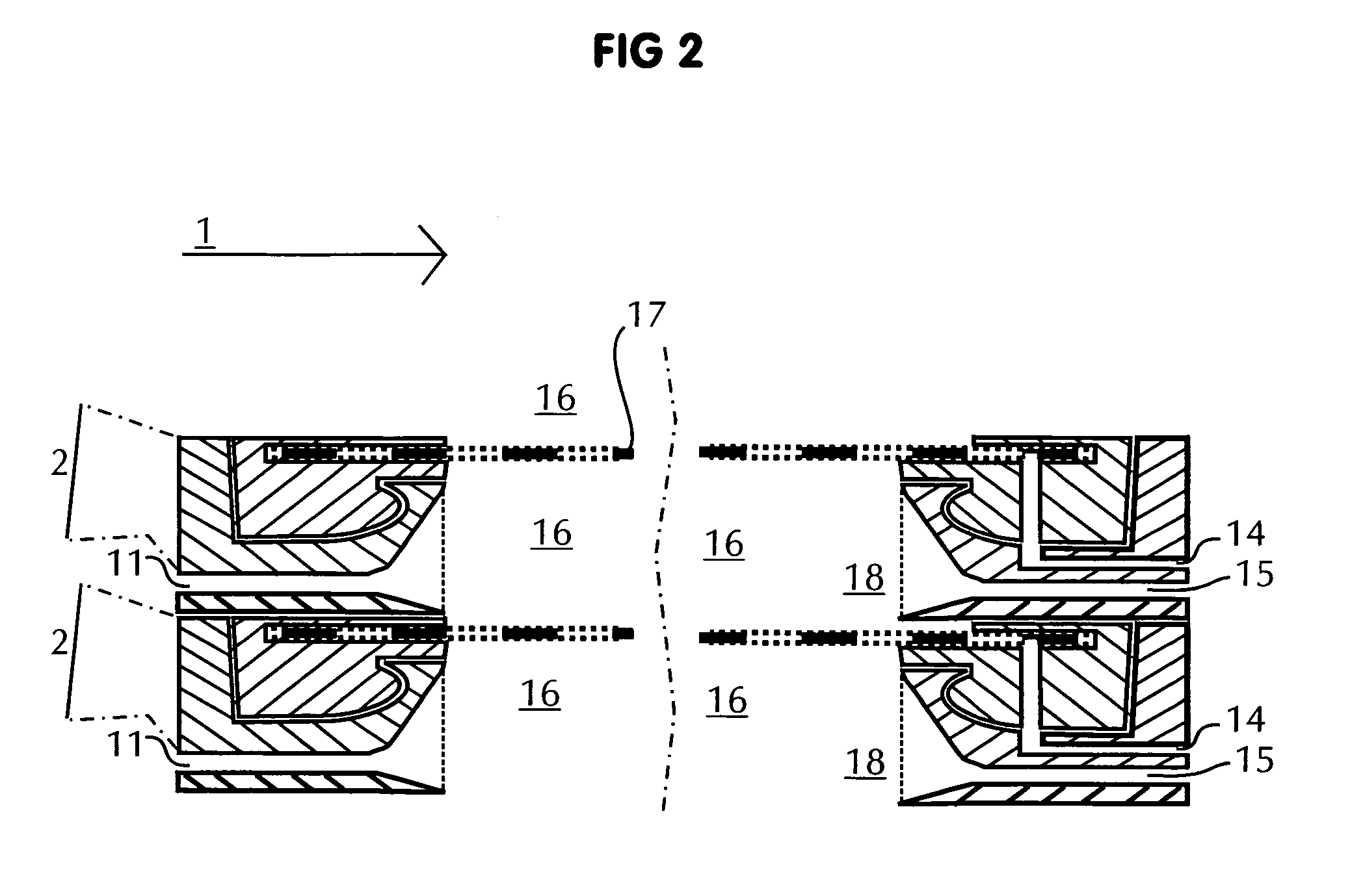
[0012] Tensioned filter elements incorporating teachings of the present invention eliminate various types of strengthening, rigidifying and / or spacing members mounted parallel to and often blocking central areas of the membranes associated with prior plate filter elements. The present invention includes positioning membrane sheets, each tensioned on at least two points across a central workspace, which workspace is thereby left substantially open and free of mechanical obstructions. This method for assembling a filter element may be generally described as tensioning a filter element.
[0013] The present invention includes tensioning or anchoring filter media to maintain structural strength required for shape-holding. The present invention also maintains pre-determined spacing between associated filter media which allows process fluid to communicate with upstream surfaces of associated filter media. The present invention allows permeate fluid to collect and flow generally uniformly within an inner space defined by any two layers of filter media.
[0014] One aspect of the present invention includes forming a filter element which allows an associated filter media to stretch, flex and / or bounce while exterior portions or periphery of the filter media remains securely anchored with other components of the filter element.

Problems solved by technology

These reciprocating orbital shaking motions may produce boundary layer turbulence or interference on upstream surfaces of each membrane or leaf element to continuously scour associated surfaces of any scaling, cake or film.

Method used


Image

  • Filtration system and dynamic fluid separation method
  • Filtration system and dynamic fluid separation method
  • Filtration system and dynamic fluid separation method

Examples


second embodiment

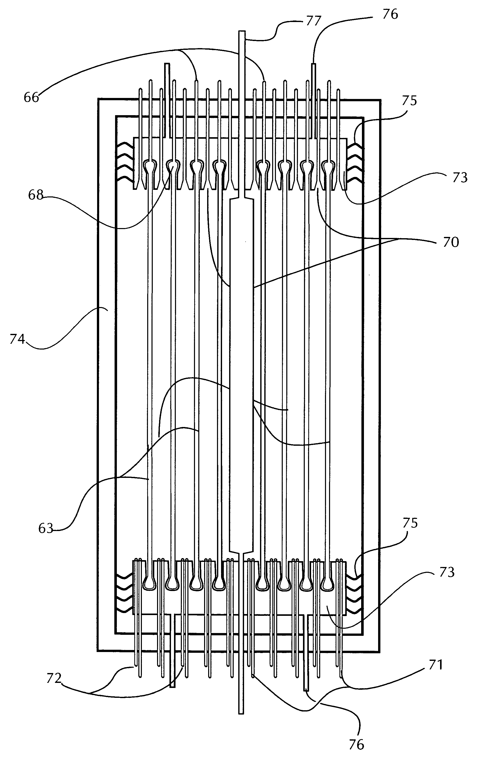
[0267]FIG. 25 shows a cut-away side view, with perspective projections of inside top and bottom of spiral end cap holders, of the flexible membrane envelope (part 63) intended for spiral wound mounting, mounted in one embodiment of a filtration system, incorporating teachings of the present invention, including an alternative technique for tensioning the flexible membrane envelope (part 63), flow paths for ingress and egress of various constituents of the filtration process, and also flow paths for injecting air bubbling parallel to all of the spiral-wound upstream membrane surfaces. Note that in this second embodiment of this construction example of tensioned, spiral wound membrane construction, the top and bottom end caps communicate relatively flexibly with the surrounding outer vessel, so as to permit said end caps to be moved reciprocatingly, up and down as shown in the figure, to vary the tensioning on the flexible membrane elements, including during dynamic filtration. This a...

third embodiment

[0313] the tensioning method for constructing a filter comprises two main elements. The first element comprises one or more flexible permeable membrane sheets, FIG. 13, 40, all of whose peripheral edges are joined by folding and or by sealing 42 to form a flexible membrane envelope 44. As with the two previous filter element embodiments, filter and plate frame, said flexible membrane envelope 44 defines a sealed inner space between the membrane sheets. In the case of this embodiment, spacing between said two membrane sheets may be maintained via flexible netting, bleed cloth or other permeable space holding elements. Provision may be made at a point or points around the periphery of such sealed flexible membrane envelopes for the egress of permeate, such as tubing or other orifices sealingly penetrating said periphery 45. In addition, means for the fastening of connecting elements between said edge and a relatively rigid outer support element, such as but not limited to grommets 45 ...


PUM

PropertyMeasurementUnit
Flow rateaaaaaaaaaa
Flexibilityaaaaaaaaaa
Shape memory effectaaaaaaaaaa

Abstract

A filtration system is provided with filter media operable to remove solids, particulate and colloidal matter from a process fluid. The filtration system may include one or more porous membranes which are anchored or secured on their periphery with a large open work area operable to remove selected components from the process fluid. The filter media may include an envelope formed from two membrane sheets with a spacer element disposed there between. A chamber or collection zone may be formed within the envelope to receive clarified fluid separated from the process fluid. Alternatively, the filter media may be multiple layers of spiral wound membranes or a roll of membranes.

Description

CROSS REFERENCE TO RELATED APPLICATIONS [0001] This application claims priority to U.S. Provisional Patent Application Ser. No. 60 / 491 / 581, filed Jul. 30, 2003, and entitled “Tensioned Leaf Filter Elements With Perpendicular Vibration.”[0002] This application also claims priority to U.S. Provisional Patent Application Ser. No. 60 / 491,579, filed Jul. 30, 2003, and entitled “Tensioned Stack Plate Filter With Perpendicular Vibration.”[0003] This application is related to copending application Serial No. ______ filed Jul. 30, 2004, entitled “Filtration System with Enhanced Cleaning and Dynamic Fluid Separation.”TECHNICAL FIELD [0004] This disclosure relates in general to the field of fluid separation, and more particularly to filtration systems and dynamic separation of a process fluid. BACKGROUND OF THE INVENTION [0005] An ongoing goal in the filtration industry is to perform filtration continuously for sustained periods, even when processing fluids with high amounts of solids or collo...

Claims


Application Information

Patent Timeline
IPC IPC(8): B01D61/00B01D63/00B01D63/08B01D63/10B01D63/16B01D65/00B01D65/02B01D65/08B01D69/02B01D69/10
CPCB01D63/00B01D63/08B01D63/081B01D63/082B01D63/10B01D63/16B01D2321/2058B01D65/02B01D65/08B01D69/02B01D69/10B01D2321/185B01D2321/2016B01D65/00B01D63/0822B01D69/1071
Inventor KIRKER, CURTISFULLER, BERKELEY F.
Owner PHASE
Learn More