Apparatus and method for molten salt electrolytic bath control

Inactive Publication Date: 2005-01-20
TOYO TANSO KK
View PDF7 Cites 13 Cited by
  • Summary
  • Abstract
  • Description
  • Claims
  • Application Information

AI Technical Summary

Benefits of technology

[0009] After the start of heating the electrolyzer to melt the solid-form electrolytic bath, the changes in state of the electrolyzer are detected using the detectors fitted to the electrolyzer and thereby whether the melting of the electrolytic bath in the electrolyzer has proceeded to a predetermined level or not is indirectly judged. Based on this judgment, the liquid electrolytic bath surface levels are adjusted, after complete melting of the bath, to a state allowing electrolysis; in this way, the molten salt electrolytic bath can be automatically and safely shifted from the solid state to a state allowing the start of the operation.
[0030] Following the adjusting step of adjusting the liquid electrolytic bath surface levels to a state allowing electrolysis, an inert gas is introduced at least into the anode chamber to thereby replace the atmosphere in the anode chamber with the inert gas. Thereafter, electrolysis is started, and the gas generated in the anode chamber is forced out of the anode chamber by means of the inert gas, the electrolysis is then continued for a certain predetermined period of time while continuing inert gas introduction and, after reduction of the moisture content in the gas generated in the anode chamber and that in the electrolytic bath to sufficiently low levels, the inert gas introduction is discontinued and the operation proper is started. As a result, the formation of OF2 resulting from reaction between oxygen gas and fluorine gas and becoming one of the factors causing explosion can be prevented and the electrolytic operation can be started safely.

Problems solved by technology

Even if, in finally judging that the extent of melting is such that electrolysis can be carried out safely, the judgment of the state of melting of the electrolytic bath is poor, it becomes possible to automatically and safely cause shifting from the state in which the molten salt electrolytic bath is in a solid form to a state in which the operation can be safely started by laying down an additional judgment criterion, verifying this based on experimental facts, rejudging of the completion of melting of the electrolytic bath based on the additional judgment criterion thus established and, after complete melting of the bath, adjusting the liquid electrolytic bath surface levels to a state allowing electrolysis.

Method used


Image

  • Apparatus and method for molten salt electrolytic bath control
  • Apparatus and method for molten salt electrolytic bath control
  • Apparatus and method for molten salt electrolytic bath control

Examples


Embodiment Construction

[0036] Now, referring to the drawings and taking the electrolyzer of a fluorine gas generator as an example of the embodiment of the molten salt electrolytic bath, the constitution of the molten salt electrolytic bath which is to be controlled according to the invention is described.

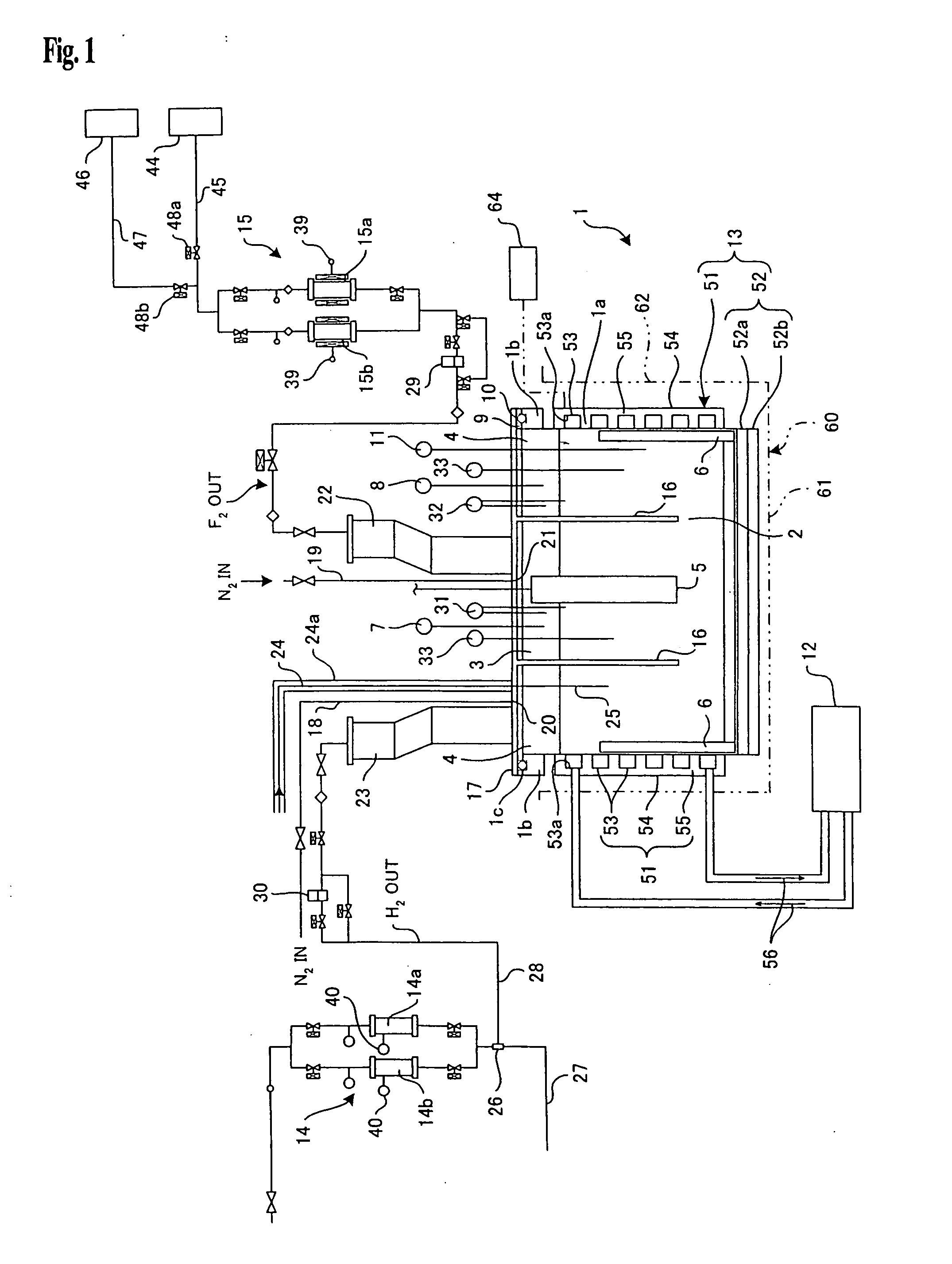
[0037]FIG. 1 is a schematic representation of the principal parts of the fluorine gas generator (molten salt electrolyzing apparatus) according to the invention. In FIG. 1, 1 is an electrolyzer constituted of an electrolyzer body 1a and an upper lid or covering 17, 2 is an electrolytic bath consisting of a fused or molten KF-HF system-based mixed salt, 3 is an anode chamber, 4 is a cathode chamber, 5 is an anode, and 6 is a cathode. 22 is an outlet port for fluorine gas generated from the anode chamber 3, and 23 is an outlet port for hydrogen gas generated from the cathode chamber 4. 11 is a temperature detector for measuring the temperature in the electrolytic bath 2, 13 is heat exchange means for the ...


PUM

PropertyMeasurementUnit
Percent by volumeaaaaaaaaaa
Electrical resistanceaaaaaaaaaa
Surfaceaaaaaaaaaa

Abstract

An apparatus for controlling a molten salt electrolyzer in which an electrolytic bath in a solid form as contained in the electrolyzer is melted to automatically attain a state allowing electrolysis, which apparatus comprises detecting means for detecting the changes in state of the electrolyzer by means of detectors fitted to the electrolyzer, and adjusting means for adjusting, after using the detecting means, the liquid electrolytic bath levels to a state allowing electrolysis.

Description

FIELD OF THE INVENTION [0001] The present invention relates to an apparatus and a method for molten salt electrolytic bath control. BACKGROUND OF THE INVENTION [0002] The molten salt electrolyzer often contains in the inside thereof a highly reactive or toxic molten salt as an electrolytic bath, and the electrolyzer is made ready for electrolysis by forming a closed space and heating the electrolytic bath to melt the salt material. The judgment as to whether the electrolyzer is ready for electrolysis as a result of completion of the melting of the electrolytic bath is made by an operator based on the electrolyzer temperature information and other information and based on his / her own experience. The electrolytic bath has a high melting point and occurs as a solid at ordinary temperature. Generally, the gaseous phase section in the electrolyzer is divided into an anode compartment or chamber and a cathode compartment or chamber by insertion of a partition wall into the electrolytic ba...

Claims


Application Information

Patent Timeline
IPC IPC(8): C25B1/24C25B15/02C25B15/00C25C7/06
CPCC25B1/245C25C7/06C25B15/00C25B15/025C25B15/08
Inventor TOJO, TETSUROHIRAIWA, JIROYOSHIMOTO, OSAMU
Owner TOYO TANSO KK
Why Eureka
Try Eureka