
Traversing measurement system for a dryer and associated method

a measurement system and dryer technology, applied in the direction of optical radiation measurement, lighting and heating apparatus, instruments, etc., can solve the problems of inability to reliably placed standard on-line moisture gauges inside the cooling section of the dryer, and inability to accurately determine the average moisture after drying and before re-ordering, etc., to reduce unnecessary deviation, prevent over-drying tobacco, and improve process control and product quality

Inactive Publication Date: 2005-01-20
INNOVATIVE TECH GRP & COMPANY LTD THE
View PDF5 Cites 11 Cited by
  • Summary
  • Abstract
  • Description
  • Claims
  • Application Information

AI Technical Summary

Benefits of technology

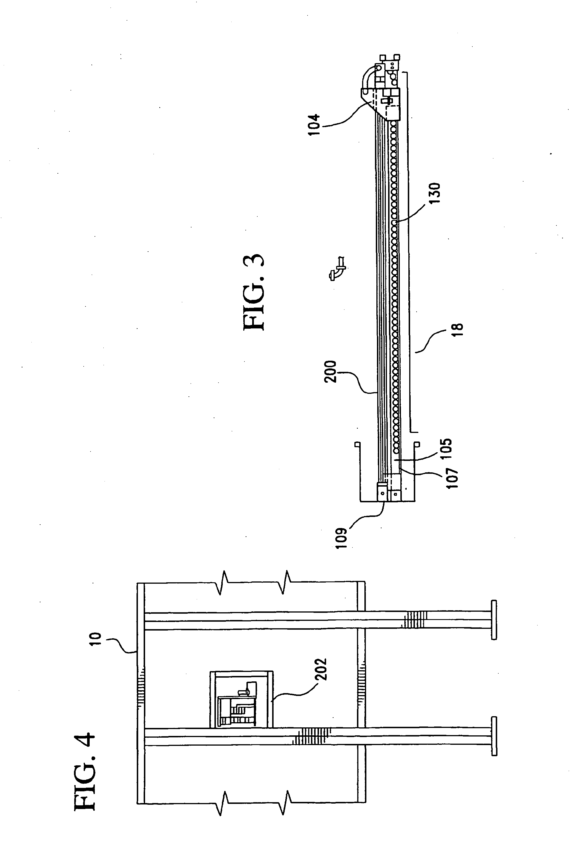
[0013] The fiber optic based measurement system provides a non-contact detection system which thus performs the measurements non-destructively. The system, which is made up of the fiber optic head, the traverse beam, the means for driving the fiber-optic head across the traverse, and the other associated parts and components, provides a very compact detector unit, which is thus capable of being installed within various types of processing equipment, thereby permitting in situ measurements to be taken and used in any manner desired, for example, as feedback information to an equipment controller.
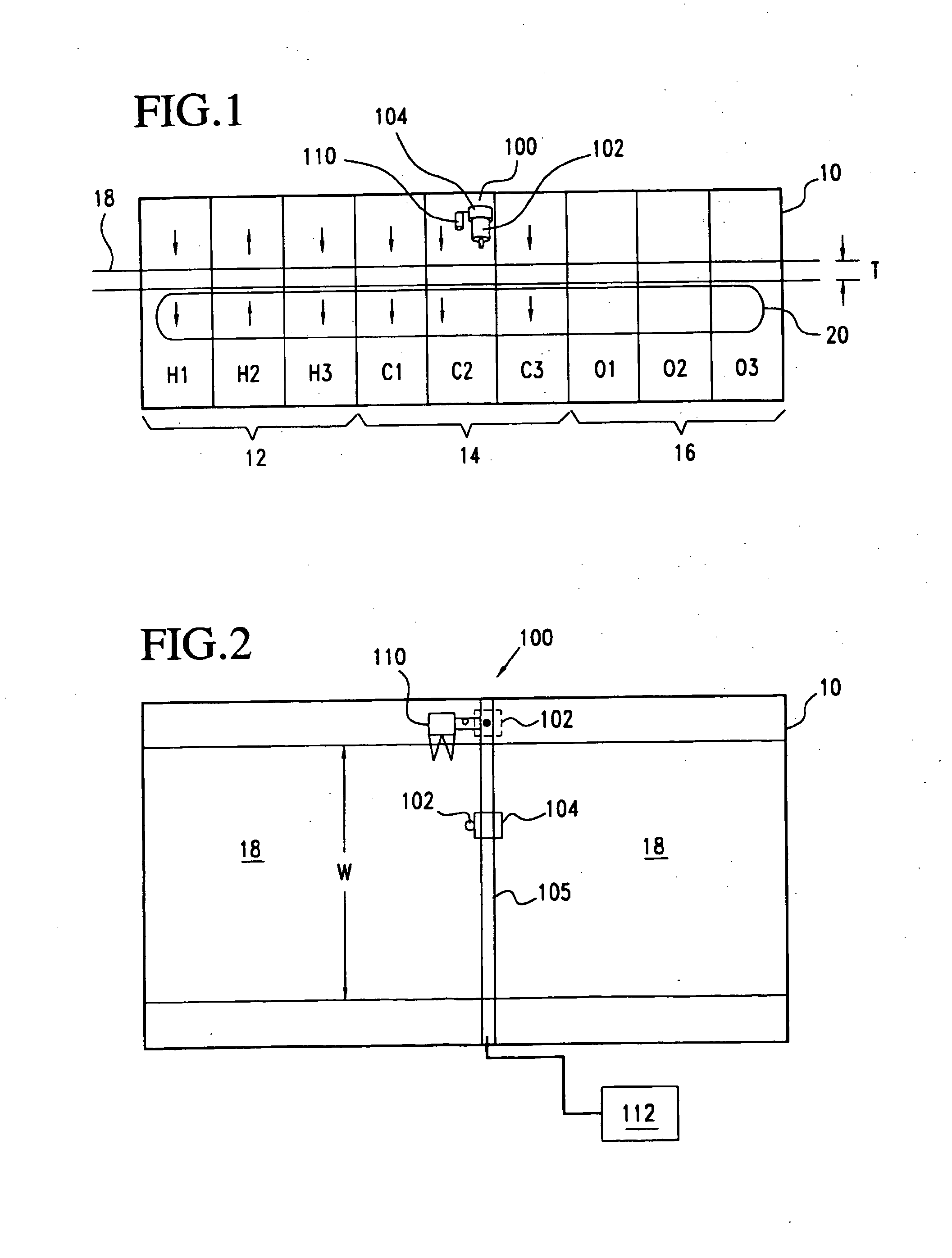
[0015] The system measures process variables / constituents on a continuous basis and collects data at specified (customer or otherwise) positions across the entire apron width. To improve repeatability, single measurement electronics is provided for each process variable (PV). The data is displayed in actual engineering units through a color touch screen display mounted in the control cabinet provided or optionally mounted up to 150′ away from the control cabinet. The system is designed to automatically trend collected data with reference to real time and develops dryer profile bar charts that are updated regularly. From the visual graphics provided, the dryer performance can be quickly reviewed so corrective action can be made. This allows improvement of the dryer's final product output consistency; thereby reducing standard deviation of the final product. In addition, the system provides real time measurements of process variables for use in both feedback and feed forward control loops providing optimum dryer performance and maximum return on investment.
[0018] The electronics package that traditionally has been provided in the same housing as the NIR optical detector components is, in the present system, disposed at the exterior of the processing equipment, and the NIR optical detector components and associated processing electronics are optically coupled by a flexible fiber-optic cable which extends from the NIR optical detector inside the processing equipment to an electronics package mounted at the exterior of the equipment. This allows the use of a much more compact detector head inside the processing equipment.

Problems solved by technology

Moisture control in apron style tobacco dryers has long been a challenge to the industry.
One major problem has been that the drying process is both multiple zone and bi-directional.
Therefore, no reliable means for determining the average moisture after drying and before re-ordering was readily available.
Some processors have placed standard on-line moisture gauges inside the cooling sections of dryers with limited success.
Mainly because it is a single point-measuring device mounted at a fixed position along the longitudinal axis of an apron style dryer, the data does not provide a true profile of the product across the entire dryer width and therefore is of limited use.
This is further complicated by the fact standard photometers (moisture gauges) in this environment are operating near or at their maximum operating temperature, affecting both their performance and life cycle (MTBF).

Method used


Image

  • Traversing measurement system for a dryer and associated method
  • Traversing measurement system for a dryer and associated method
  • Traversing measurement system for a dryer and associated method

Examples


Embodiment Construction

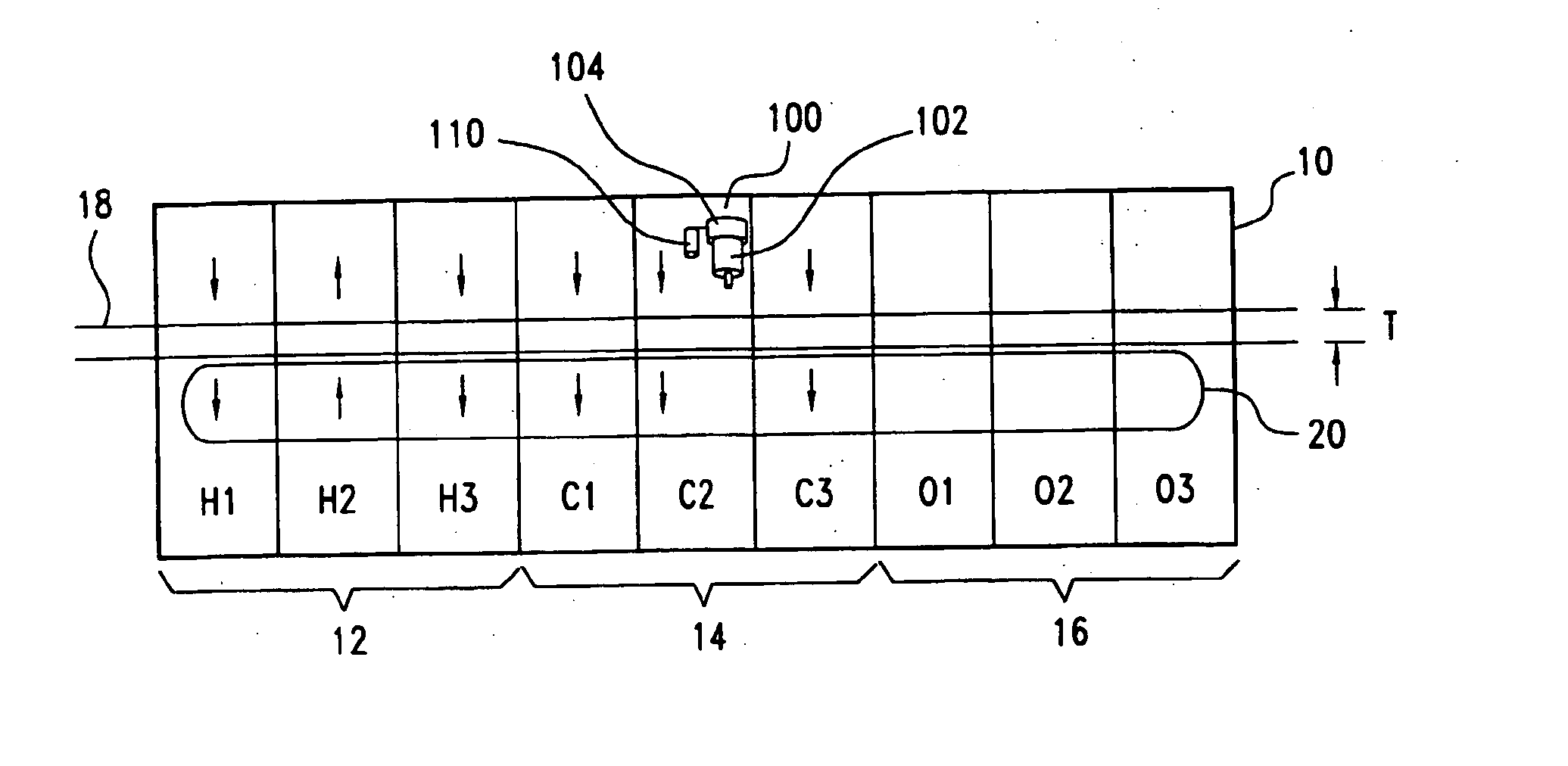
[0029] Referring initially to FIGS. 1 and 2, a measurement system 100 is shown in schematic form as installed internally in what is referred to in the tobacco processing industry as an apron dryer 10. It is to be noted that the discussion of the invention as used in connection with an apron dryer, and in connection with the drying of tobacco, is solely for illustrative purposes, as the measurement system can readily be incorporated into any number of types of processing equipment, and is suitable for use in any applications in which a product properly or properties can be correlated to the emanation / reflection from the product of near-infrared (NIR) energy.

[0030] As other examples in the processing of tobacco, near-infrared energy reflected from the surface of the tobacco product can be used to determine the nicotine content of the tobacco, the sugar content, and / or the fat content, as well as other properties. A signature reflected energy pattern can readily be developed for each ...


PUM

PropertyMeasurementUnit
widthaaaaaaaaaa
widthaaaaaaaaaa
lengthaaaaaaaaaa

Abstract

A system and method for obtaining measurements across a width of material being processed is provided, which includes a near-infrared (NIR) detector head (102) which reads and transmits an NIR signal that has been reflected from the material, and a fiber-optic cable (106) through which the signal is transmitted to a processor located remotely from the material being processed. A moisture level reading can be obtained in a drying apparatus and used to aid in controlling the operation of the dryer. The detector head (102) is mounted to a traversing beam (105) and the detector head (102) is capable of traveling to positions across the width of the material being processed.

Description

BACKGROUND OF THE INVENTION [0001] 1. Field of the Invention [0002] This invention is directed to a system and method for obtaining measurements across the width of a material being dried in an industrial dryer. [0003] 2. Description of Related Art [0004] Industrial dryers are used, for example, in drying tobacco in various processed forms prior to the tobacco being used in producing finished products. Other products also require drying as part of the processing to produce the final product. In certain tobacco drying processes, for example, an “apron”, or substantially continuous moving sheet, of tobacco in semi-processed condition is passed through dryer units at one or more stages prior to packaging for shipment to a tobacco products manufacturer. The tobacco is checked for moisture content after it has been processed through the dryer, in order to determine whether the moisture level of the tobacco is at or below the maximum moisture level as dictated by the tobacco products manu...

Claims


Application Information

Patent Timeline
Patent Type & Authority Applications(United States)
IPC IPC(8): A24B9/00F26B25/22G01N21/35G01N21/89
CPCA24B9/00F26B25/22G01N21/3554G01N21/3559G01N21/89G01N21/8914G01N21/359
Inventor RAE, TODD A.
Owner INNOVATIVE TECH GRP & COMPANY LTD THE
Learn More