Eureka AIR delivers breakthrough ideas for toughest innovation challenges, trusted by R&D personnel around the world.

Mask cost driven logic optimization and synthesis

a logic optimization and mask cost technology, applied in the field of mask design, can solve the problems of small silicon cost, and dramatic increase in mask set cos

Inactive Publication Date: 2004-10-21
SYNOPSYS INC
View PDF3 Cites 15 Cited by
  • Summary
  • Abstract
  • Description
  • Claims
  • Application Information

AI Technical Summary

Benefits of technology

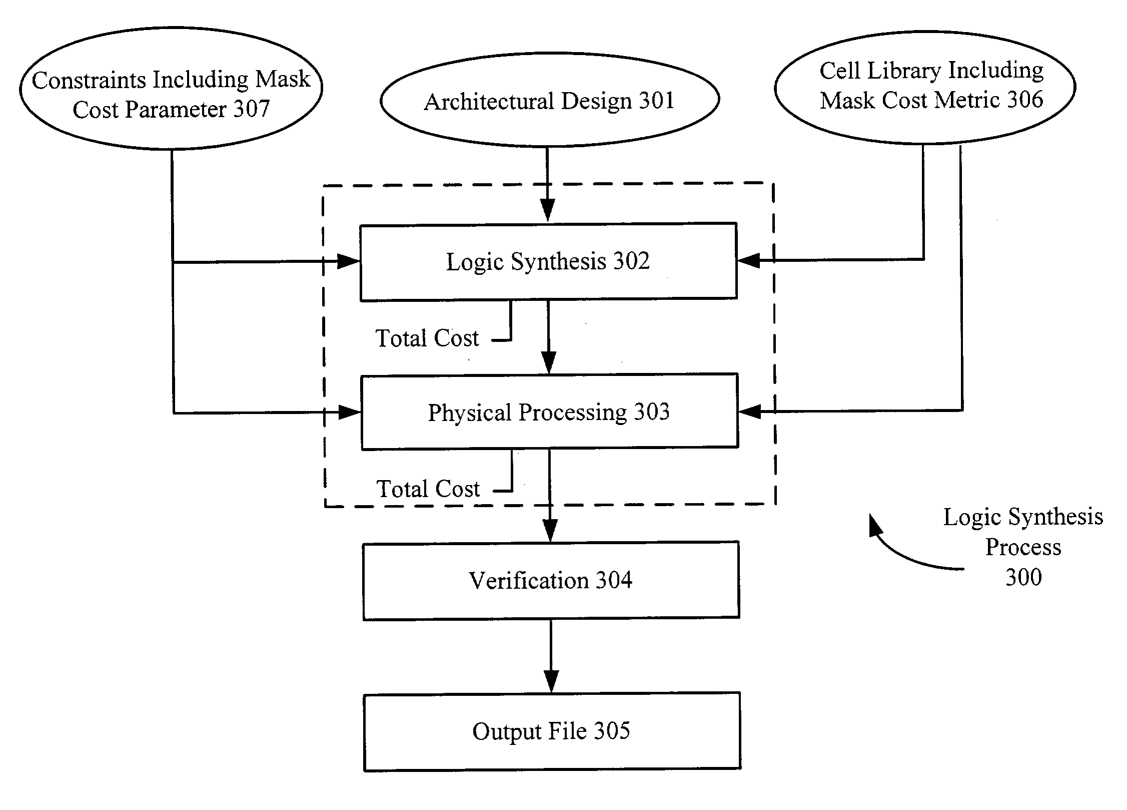
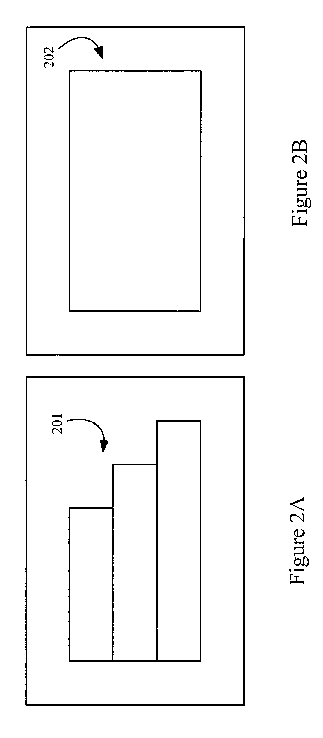
[0013] In one embodiment, the mask cost metric can account for a characteristic of a mask writing tool, such as exposure type. For example, the mask cost metric associated with a vector scan mask writing tool could be different than a mask cost metric associated with a raster scan mask writing tool. In another embodiment, the mask cost metric can account for an amount of optical proximity correction (OPC) features provided in a cell. For example, the more OPC applied to a cell could result in a higher mask cost metric. In yet another embodiment, the mask cost metric can account for an amount of phase-shifted features provided in a cell. For example, the more phase shifting applied to a cell could result in a higher mask cost metric.

Problems solved by technology

Unfortunately, mask set cost has dramatically increased due to demand for even smaller device sizes as well as chip complexity.
The cost of making a mask set cost has been dramatically increasing due to demand for very small device sizes as well as higher chip complexity.
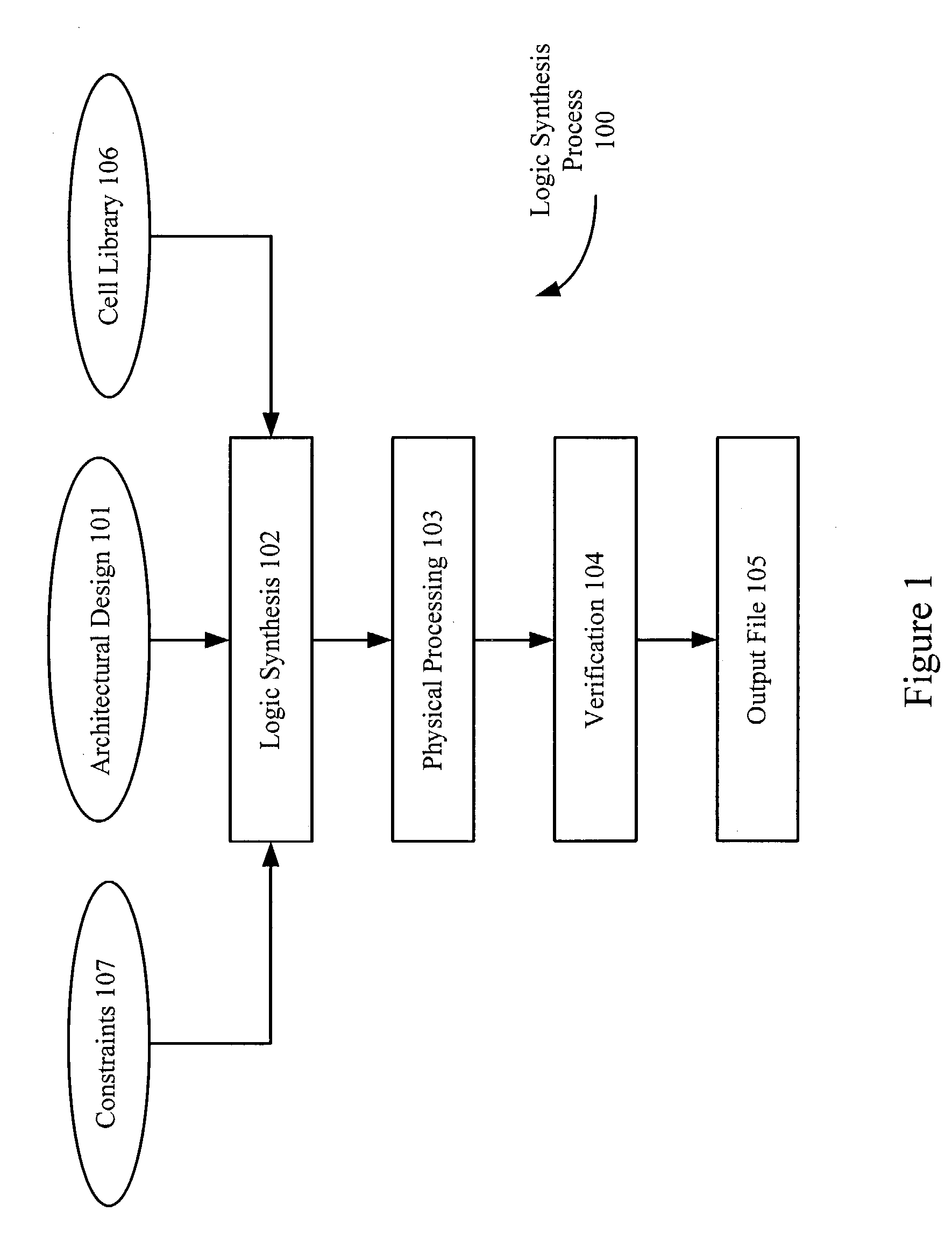
However, current logic synthesis tools create mask designs based on IC characteristics, e.g. speed, area, and power consumption.
Unfortunately, performing logic synthesis to minimize area, for example, would probably lead to smaller silicon cost, but might actually increase mask costs.
For example, the more OPC applied to a cell could result in a higher mask cost metric.
For example, the more phase shifting applied to a cell could result in a higher mask cost metric.

Method used


Image

  • Mask cost driven logic optimization and synthesis
  • Mask cost driven logic optimization and synthesis
  • Mask cost driven logic optimization and synthesis

Examples


Embodiment Construction

[0048] Although illustrative embodiments of the invention have been described in detail herein with reference to the figures, it is to be understood that the invention is not limited to those precise embodiments. They are not intended to be exhaustive or to limit the invention to the precise forms disclosed. As such, many modifications and variations will be apparent. For example, in one embodiment, the mask cost could include inspection and repair costs in addition to writing costs. For example, the more exposure polygons used during mask writing, the more phase shifted features, and / or the more OPC features provided in the cell (i.e. the level of complexity associated with the cell), the greater the probability that increased inspection time and additional repairs could be needed. Therefore, the associated inspection and repair costs could also be factored into the mask cost metric for each cell. Note that the mask writing techniques described herein can be applied to any lithogra...


PUM


Abstract

The cost of making a mask set cost has been dramatically increasing due to demand for very small device sizes as well as higher chip complexity. Thus, users would like to minimize the total mask costs. Current logic synthesis tools can create mask designs based on IC characteristics, e.g. speed, area, and power consumption. Therefore, a method of providing a mask design that can be optimized for cost is described. This method includes accessing cells from a library, wherein each cell includes a mask cost metric. Additionally, the weightings of one or more parameters in a constraints listing can be determined. Of importance, at least one parameter relates to mask cost. At this point, logic synthesis can be performed on the design using both the cells and the constraints listing. Advantageously, the resulting synthesized design can be optimized for mask cost.

Description

[0001] 1. Field of the Invention[0002] The present invention relates generally to a mask design and, in particular to the logic optimization and synthesis of that design based on cost.[0003] 2. Related Art[0004] As integrated circuits become increasingly complex, engineers are increasingly using electronic design automation (EDA) tools, such as logic synthesis tools, to convert architectural designs, which describe desired circuits and their interconnection on an integrated circuit, into mask layouts. FIG. 1 illustrates a conventional logic synthesis process 100. In process 100, an architectural design 101, which describes features of the integrated circuit, can be provided. This architectural design 101 can be written in a Hardware Description Language (HDL), such as VHDL or Verilog. In step 102, a compiler tool can perform a logic synthesis (also called a compile) of architectural design 101. To perform this function, the compiler receives architectural design 101 as well as infor...

Claims


Application Information

Patent Timeline
IPC IPC(8): G06F17/50
CPCG06F17/5045G06F17/5068G06F30/39G06F30/30G06F30/398
Inventor SANIE, MICHAELPRAMANIK, DIPANKARLIPPINCOTT, SUSAN JENNIFER
Owner SYNOPSYS INC
Why Eureka
Eureka Blog
Learn More