Method and device for self-contained inertial vehicular propulsion

Inactive Publication Date: 2010-09-30
GUTSCHE GOTTFRIED J
View PDF24 Cites 8 Cited by
  • Summary
  • Abstract
  • Description
  • Claims
  • Application Information

AI Technical Summary

Benefits of technology

[0008]It is another objective of the invention to provide an inertial propulsion device with a high degree of efficiency.

Problems solved by technology

Clockmakers were confronted by an intriguing problem.
Previous known art of self contained inertial propulsion devices using independent linear moving flywheels or other inertia elements develop comparatively low energy propulsion thrusts or high degree of vibration compared to the energy input and size of the machines.

Method used


Image

  • Method and device for self-contained inertial vehicular propulsion
  • Method and device for self-contained inertial vehicular propulsion
  • Method and device for self-contained inertial vehicular propulsion

Examples


Embodiment Construction

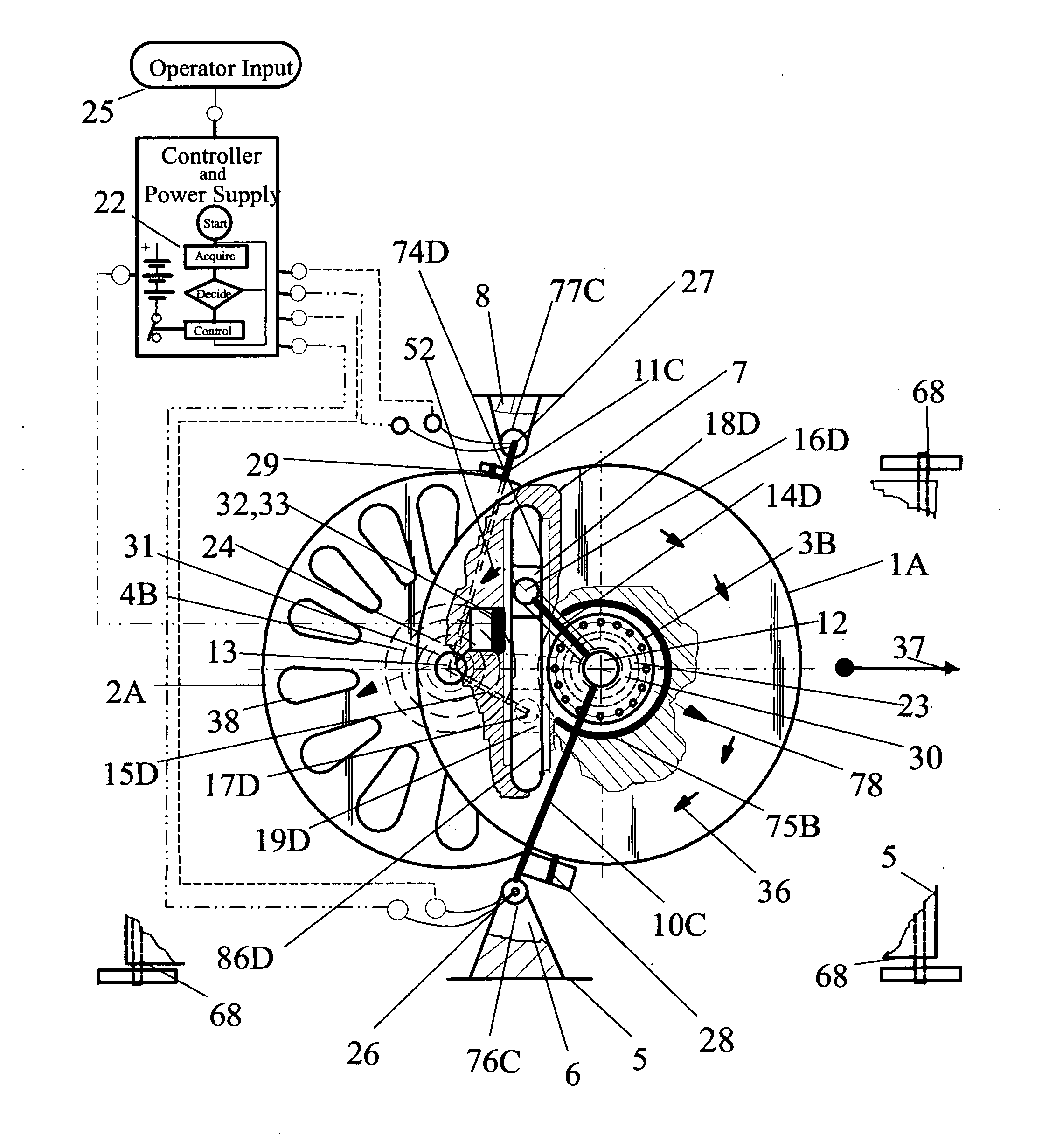
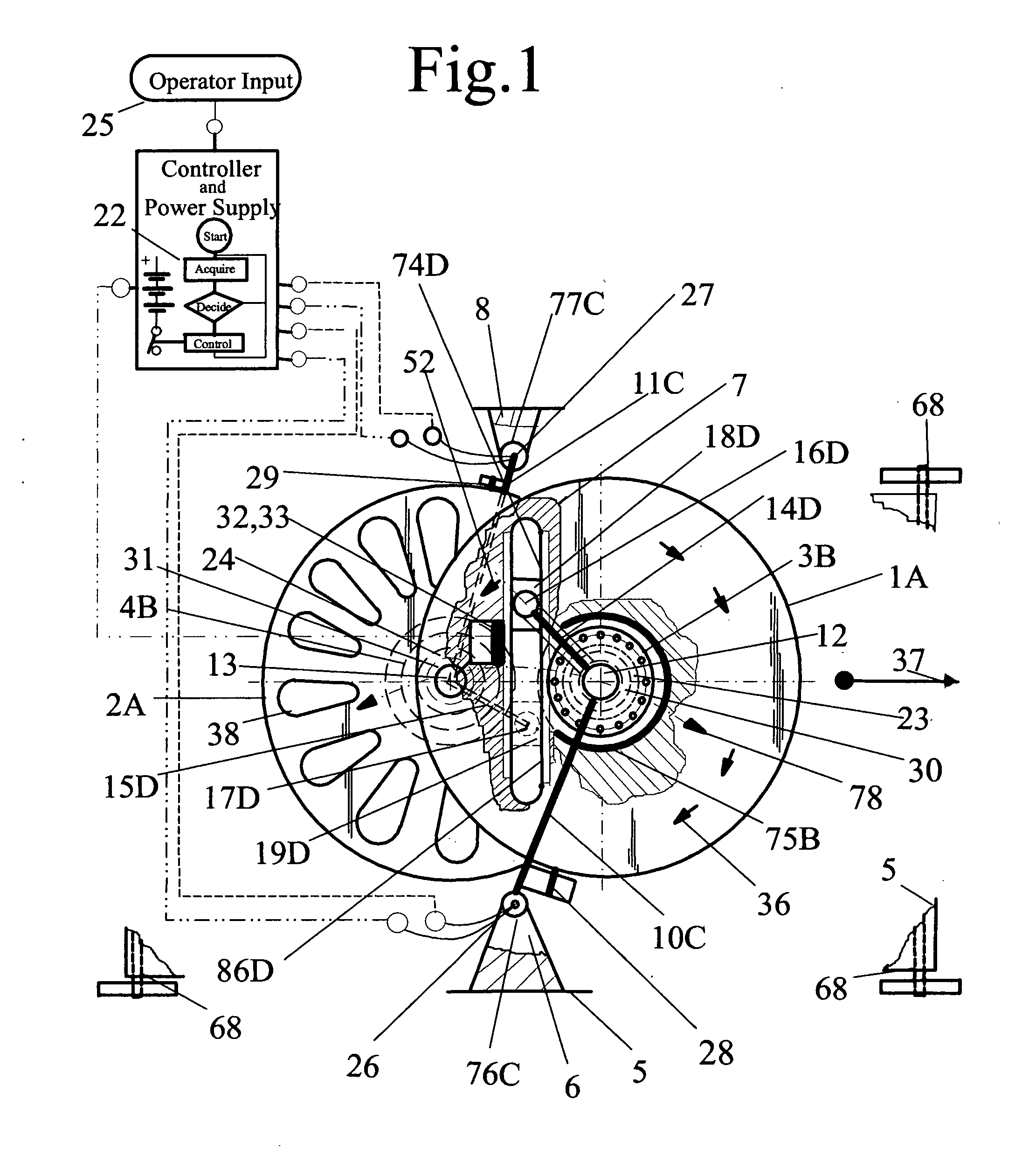
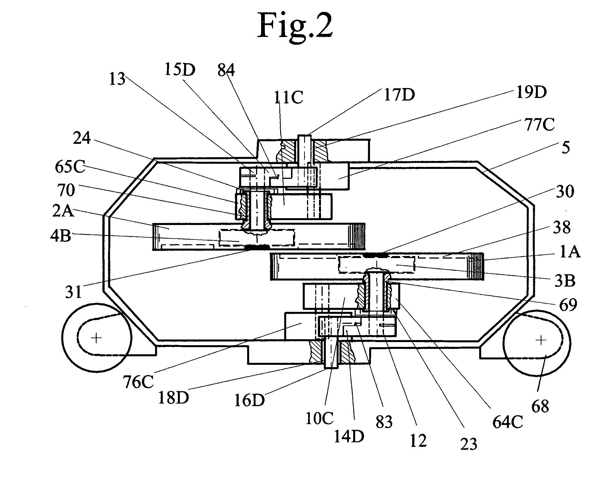
[0022]Referring to FIG. 1, the self-contained propulsion device comprising pairs of flywheels, 1A and 2A, having parallel axial orientation and linear displaceable axial spacing. Each individual flywheel of the flywheel pair, in comparison to each other axis, have a linear mutual separating motion 78 followed by a re-approaching motion 78 and opposite direction of rotation 36, therefore, the linear motion of the flywheel pair is a kinetic energy dependent mutual time sequential diametrically opposing alternating linear motion. The linear and rotational motion of the flywheels are progressively changing non-uniform movements which accomplishes the net potential energy work output propulsion thrust drive propelling the vehicles' (68) motion. The opposite direction of flywheel rotation accomplishes the cancellation of rotational torque, which prevents the turning of the device around its axis. The turning action, however, is used to steer the device by varying the rotational parameters...


PUM


Abstract

Self-contained timely sequential inertial thrust drive pulses are generated by a tandem mechanical frequency modulated oscillator using the combined effort of linear and rotational inertial reluctance contained in the mass of paired flywheels. The flywheels are having parallel axial orientation with linear displaceable spacing, opposite free wheeling rotation and opposite alternate cyclic machine-logic optimized non-uniform reciprocal motion in union with vehicular travel direction. The combined effort of linear and rotational flywheel motion accomplishes the cyclic realignment of the flywheel motion into one timely gradient vector sum motivating thrust drive. A flywheel integral regenerative drive and rotor within each flywheel are used to obtain the cycle frequency modulation and non-uniform motions. The cyclic sum of all mutual reciprocal mass motion energy transactions represents a closed loop complex Cartesian grid motion with one self-contained superior centripetal inertial thrust drives pulse per each rotor cycle.

Description

[0001]This is a Continuation-in-part (C.I.P) specification for original application Ser. No. 11 / 544,722FIELD OF THE INVENTION[0002]The present invention relates to a device and method for developing a self-contained timely sequential potential energy work output thrust drive in a predetermined direction, using the combined effort of rotational and linear kinetic energy of pairs of flywheel inertial mass motions, wherein the flywheel kinetic energy is provided by regenerative drive means under control of machine logic. The effective work output thrust drive is the product of potential energy performing work multiplied by the time duration of the motion and then dividing the product by the motion distance. The effective thrust drive magnitude, when considering the magnitude of the inertial mass, is the square root out of the product of the averaging constant multiplied by the inertial mass then multiplied by the magnitude of the potential kinetic energy performing work on the mass.BAC...

Claims


Application Information

Patent Timeline
IPC IPC(8): F16H33/08
CPCY10T74/18528F03G3/08F03G7/10F03G7/125
Inventor GUTSCHE, GOTTFRIED J.
Owner GUTSCHE GOTTFRIED J
Why Eureka
Try Eureka