Porous electrode, solid oxide fuel cell, and method of producing the same
a solid oxide fuel cell and porous electrode technology, applied in the manufacture of final products, cell components, electrochemical generators, etc., can solve the problems of inability to prepare cu-ysz cermets, stringent requirements for fabrication materials, and limited materials used to fabricate respective cell components
- Summary
- Abstract
- Description
- Claims
- Application Information
AI Technical Summary
Benefits of technology
Problems solved by technology
Method used
Image
Examples
example 1
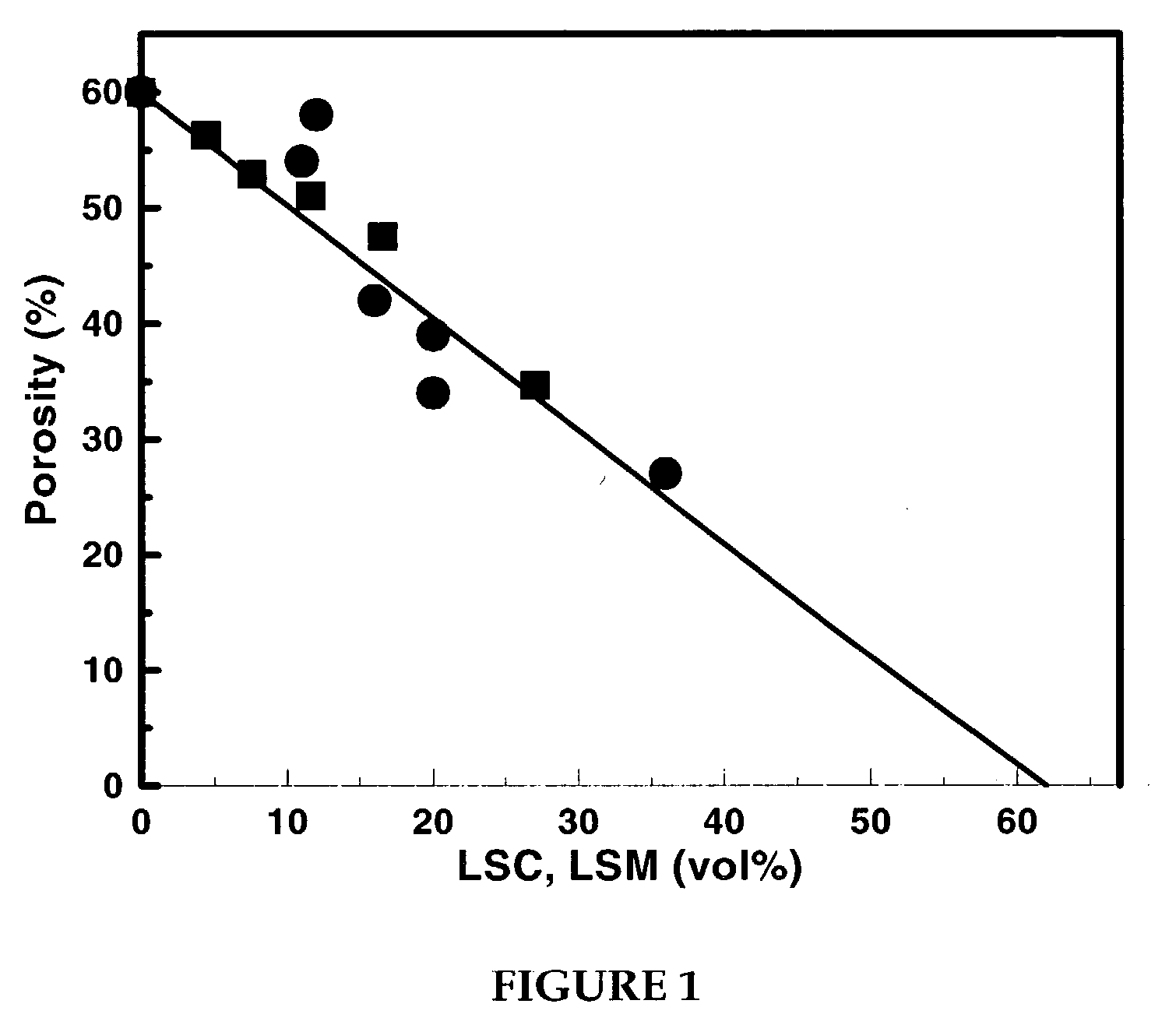
[0066] A series of porous composites were prepared in accordance with Method b above to determine whether the electronically conducting oxide material was being dispersed within the porous matrix. The porosities of a series of materials with increasing amounts of LSM or LSC were measured, with the results shown in FIG. 1. The LSC--YSZ composites in this figure were calcined to 1,100.degree. C. and the LSM-YSZ composites were calcined to 1,250.degree. C. For these data, the volume of the conducting oxide was determined from its mass and bulk density. The line in the figure is the expected change in porosity of the composite assuming the second oxide fills the pores. The fact that the porosity decreases as expected demonstrates that the electronically conducting oxide material is present in the pore structure following the calcination treatments.
[0067] As shown in FIG. 1, the porosity of the LSC--YSZ composite decreases from 60% by volume (e.g., porosity of YSZ matrix) at 0% LSC, to 0...
example 2
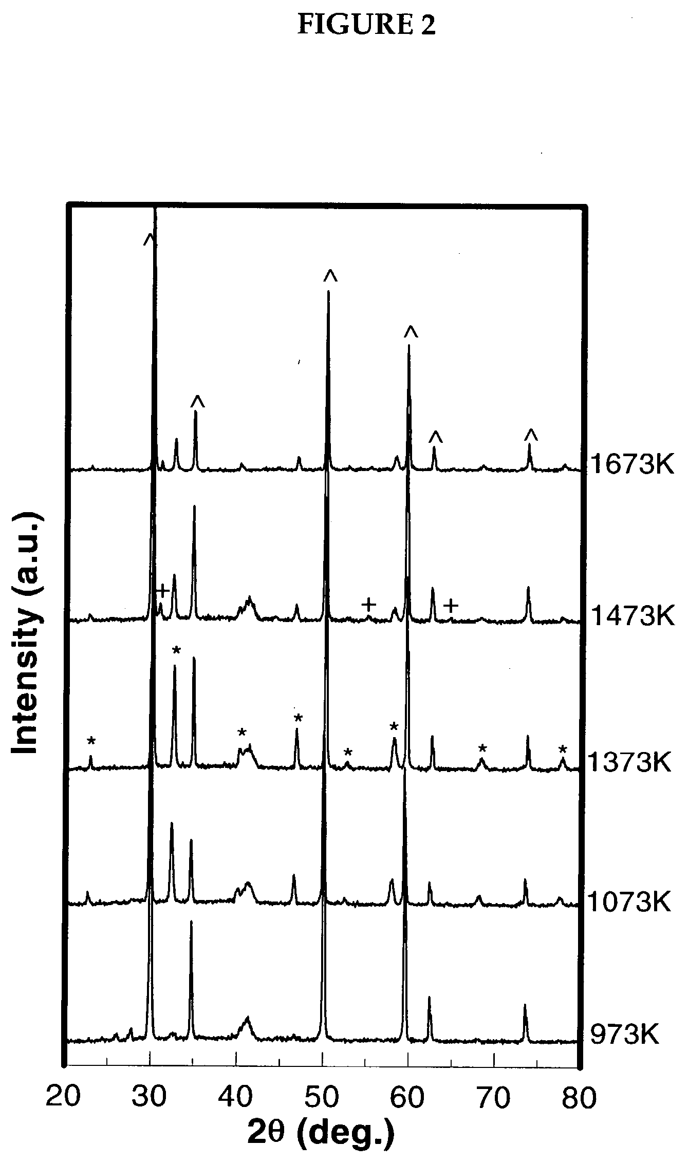
[0068] LSC--YSZ composites that preferably can be used as an anode material were prepared in accordance with method b above. To determine the optimum calcination temperature, method b was repeated at different temperatures, the results of which are shown in FIG. 2. FIG. 2 shows the XRD patterns following impregnation of the porous YSZ with the La, Sr, and Cr salts to a loading that would correspond to about 30 vol wt % LSC, after calcining to increasingly higher temperatures. Peaks corresponding to the LSC, perovskite phase (notably, those at 41, 46, 58, 68, and 78 degrees 2.theta.) become apparent beginning at approximately 800.degree. C. These peaks become sharper after calcination to 1,100.degree. C., but new phases appear at still higher calcination temperatures. By 1,200.degree. C., a peak appears at 31 degrees, which is believed to be attributed to the formation of SrZrO.sub.3. For calcination temperatures below 1,400.degree. C., there are also several overlapping peaks in the...
example 3
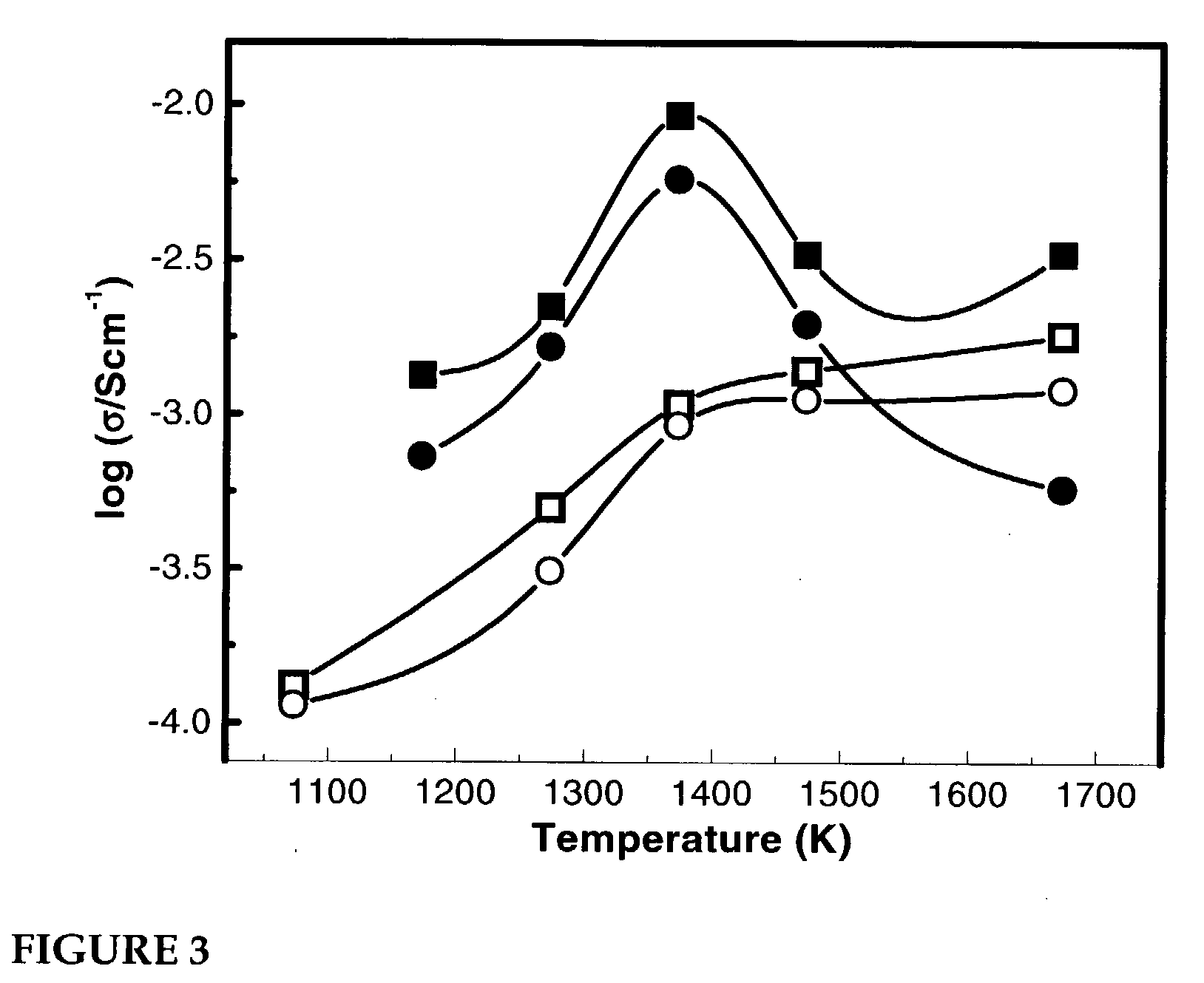
[0069] The purpose of this example was to study the effect of calcination temperature on the electronic conductivity of the composite, the results of which are shown in FIG. 3. Two LSC--YSZ composites were prepared, both having 30 vol % LSC, but one prepared using method a and the other prepared using method b described above. The samples were calcined in air for 2 hours at various temperatures before measuring the conductivities 700.degree. C. in both air and humidified H.sub.2. For the composite prepared in accordance with method b, the conductivity was found to increase with temperature to a maximum value at or about 1,100.degree. C., and then to decrease at still higher calcination temperatures. This is consistent with the formation of an LSC phase at 1,100.degree. C., followed by formation of secondary phases at higher temperatures. It also is interesting that the conductivity of the composite formed at the highest temperature is sensitive to the gas-phase composition, while th...
PUM
 Abstract
Description
Claims
Application Information
 - R&D Engineer
- R&D Manager
- IP Professional
- Industry Leading Data Capabilities
- Powerful AI technology
- Patent DNA Extraction
Browse by: Latest US Patents, China's latest patents, Technical Efficacy Thesaurus, Application Domain, Technology Topic, Popular Technical Reports.
© 2024 PatSnap. All rights reserved.Legal|Privacy policy|Modern Slavery Act Transparency Statement|Sitemap|About US| Contact US: help@patsnap.com


