Fiber optic real time display system

a fiber optic and real-time display technology, applied in the field of fiber optic real-time display systems, can solve the problems of inconvenient use of fixed content displays, inability to display images in real-time, and number of deficiencies,

Inactive Publication Date: 2004-07-29
SOLNTSEV ALEXANDER
View PDF5 Cites 4 Cited by
  • Summary
  • Abstract
  • Description
  • Claims
  • Application Information

AI Technical Summary

Benefits of technology

[0010] It is another object of the present invention to provide a real time display system reducing the difficulty of fabrication of a fiber optic display system by eliminating the requirement of assembling the fibers at high densities at the image generating source.
[0012] It is still another object of the present invention to provide a real time display system utilizing a two-dimensional viewing surface in combination with other components arranged in a three-dimensional space thereby altering the alignment of those components in relation to the viewable surface.
[0013] It is yet another object of the invention to provide a real time display system including a display having small pixel diameters on the viewable surface forming high pixel densities enabling display of high definition images.

Problems solved by technology

These fixed content displays are not suitable or practical to be used for real time images.
The LHD fiber optic devices are suitable as image display systems, but they suffer from a number of deficiencies.
The primary deficiency of these systems is that image quality of the displayed image cannot exceed the image quality of the image being generated by the source.
Another deficiency found in prior art devices is that projection of the image onto high-density fibers can suffer from misalignment between pixels of the projector and the individual fiber strands of the bundle.
It can be argued that such solutions have not been shown sufficiently practical since the individual components of such techniques, when applied as a whole, present many difficulties.
A particular problem is with the tripling of the amount of fiber to deliver an RGB output when coating different strands with each RGB component.
This can be compensated by coating the same strands with all RGB components, but at the expense of increase in difficulty of fabrication.

Method used


Image

  • Fiber optic real time display system
  • Fiber optic real time display system
  • Fiber optic real time display system

Examples


Embodiment Construction

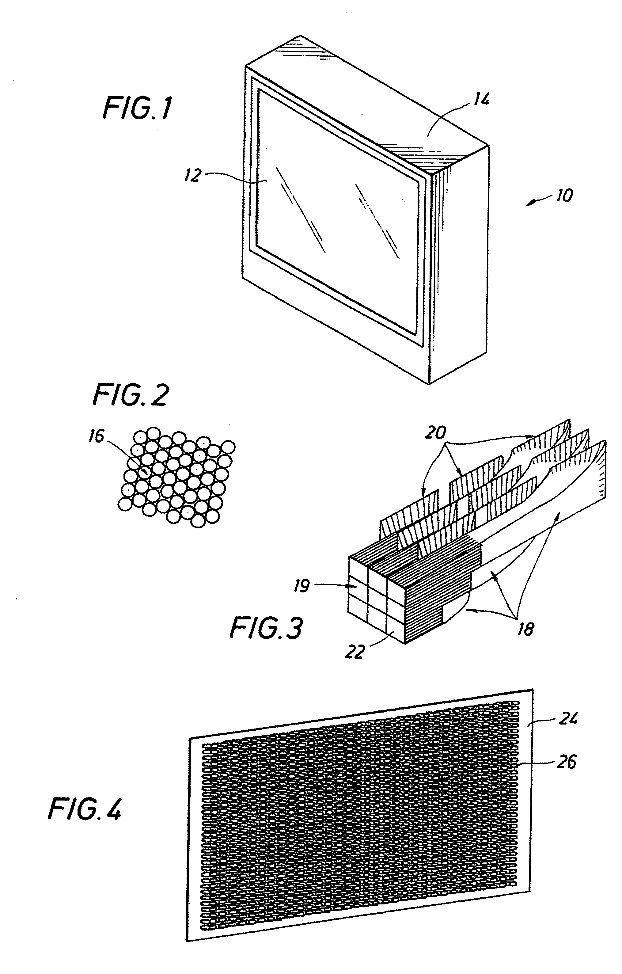
[0024] Referring first to FIG. 1, the fiber optic real time image display device of the invention is generally identified by the reference numeral 10. The display device 10 includes a fiber optic display 12 enclosed in an enclosure or casing 14. The shape of the casing 14 shown in FIG. 1 is for illustrative purposes. It is understood that the casing 14 may be any shape or size manufactured using well known techniques and materials to meet the desired specifications for housing the components of the display device 10. A semi-circular shape may be used to allow for the central viewing point to be located equal at distance to the viewing surface.

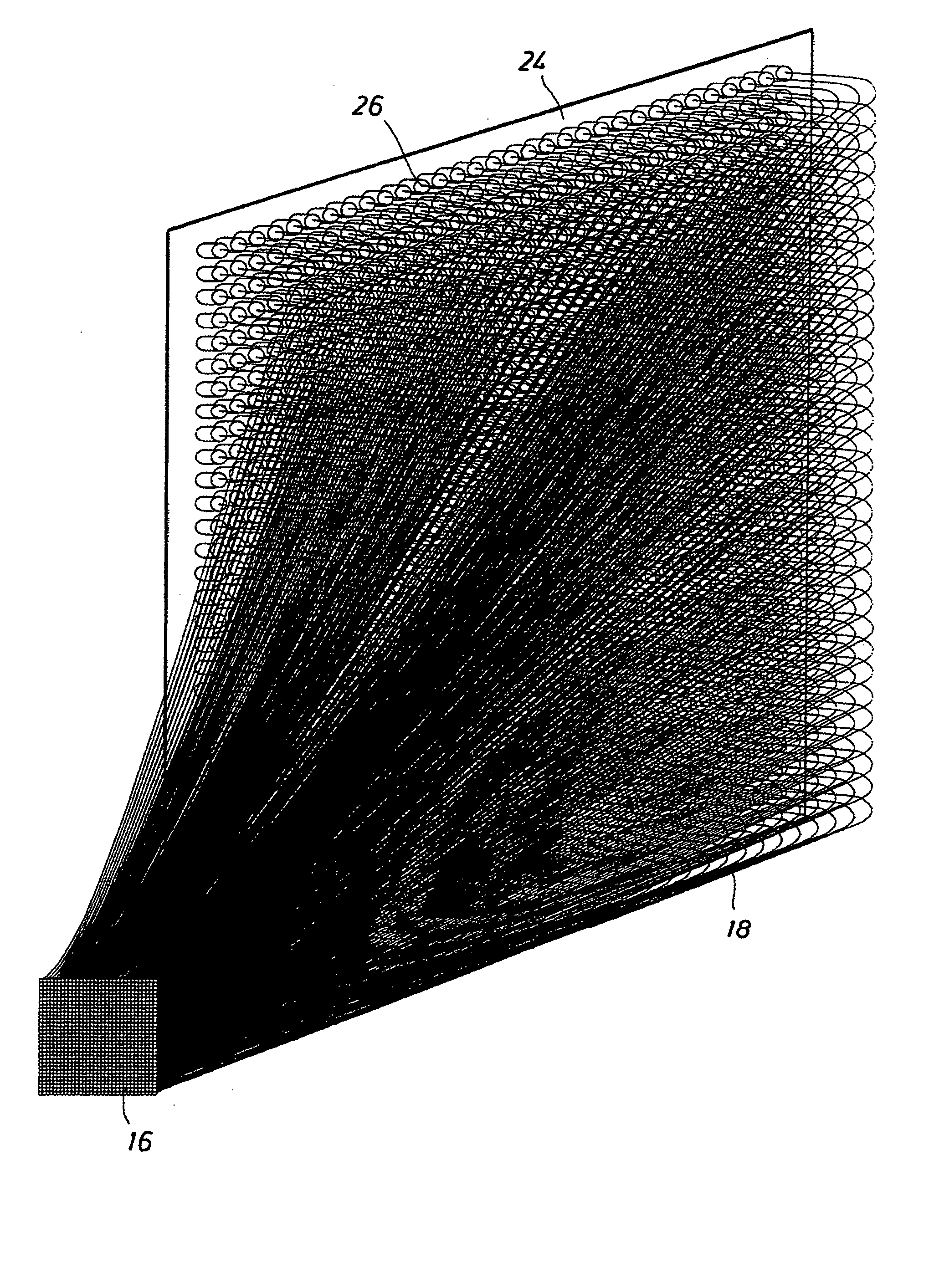
[0025] The fiber optic display 12 comprises an array of pixels 16 organized into a mesh pattern, for example, as shown in FIG. 2. The array of pixels 16 forms a continuous surface that may be flat, concave, or convex. The pixels 16 generate an optical image by free-emitting light into space either directly or through a translucent material with...


PUM


Abstract

In a fiber optic display system an array of pixels form a continuous viewable surface. Each pixel is formed by a bundle of one or more optical fibers which vector light to the pixels from one or more light sources. High density of pixels at the viewable surface is achieved by bundling small diameter optical fibers adapted for vectoring light from low density light sources. The two-dimensional geometry of the viewable surface is de-coupled from the light source which is arranged in a three dimensional space. The arrangement of light source into three dimensional space is accomplished by partitioning the light source into an array of light source planes. The arrangement of light source into a three dimensional array allows for the combined surface area of the planes to substantially exceed the display area of the viewable surface.

Description

[0001] This application is a continuation-in-part application of U.S. patent application Ser. No. 09 / 665,566 filed Sep. 19, 2000, U.S. Pat. No. 6,628,867.BACKGROUND OF THE DISCLOSURE[0002] The present invention relates to display systems, in particular, to display systems presenting real time high-definition images over a large viewing area viewable at short distances and wide angle.[0003] The prior art in the field of fiber optic display systems can be partitioned into two distinct groups: fixed content, and real time displays. The fixed content fiber optic displays encompass the devices whose image content is predetermined prior to their operation, and either does not change or has a repeating cycle during operation. These devices include a variety of lighted signs, decorative devices, and many others. These fixed content displays are not suitable or practical to be used for real time images.[0004] Real time fiber optic displays encompass a device whose image content is generated ...

Claims


Application Information

Patent Timeline
Patent Type & Authority Applications(United States)
IPC IPC(8): G02B6/36G02B6/42
CPCG02B6/06G02B6/3668G02B6/4298G02B6/368G02B6/3672
Inventor SOLNTSEV, ALEXANDER
Owner SOLNTSEV ALEXANDER
Why Eureka
Try Eureka