
Method and device for detecting fundamental natural modes of vibration of an eye, by laser interferometry, and their use for measuring intraocular pressure

a natural mode and eye technology, applied in the field of laser interferometry and the detection of fundamental natural modes of eye vibration, can solve the problems of eye trauma, eye vibration, eye vibration, etc., and achieve the effects of less constraining eye positioning, less sensitive, and less power laser

Inactive Publication Date: 2004-03-11
CENT HOSPITALER & UNIV DE LILLE +3
View PDF4 Cites 10 Cited by
  • Summary
  • Abstract
  • Description
  • Claims
  • Application Information

AI Technical Summary

Benefits of technology

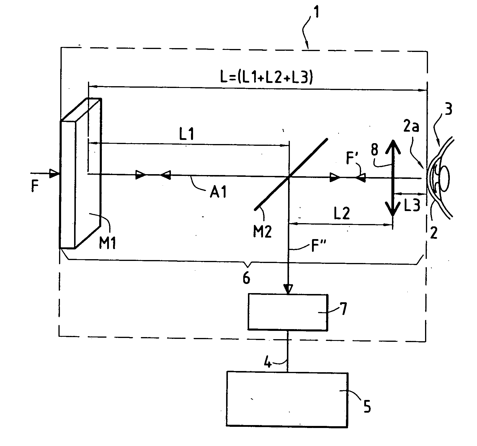
[0011] The invention seeks to propose a novel method of using laser interferometry to detect one or more natural modes of vibration of an eye, but which compared with the above-described methods based on using a Michelson type interferometer, presents the main advantages of being less constraining on eye positioning, of being less sensitive to external disturbances, and in particular mechanical vibration, and of making it possible to use a lower power laser.

Problems solved by technology

The major drawback of indentation tonometry is that account needs to be taken of the stiffness of the eye wall, and this leads-to variability of measurement from one eye to the other.
The main drawback of that tonometer is that it is traumatizing and painful when used on the eye since a mechanical deformation force is applied to the cornea.
As a result, repeated measurements on the same eye can lead to a lesion of the corneal epithelium, and in practice that method must necessarily be implemented by an ophthalmological doctor with the eye being anesthetized locally by means of anesthetic eyedrops.
In spite of providing satisfactory sensitivity, there are also numerous causes of error in measurement: variability associated with tears, with accommodation, with thickness of the cornea.
That type of tonometer likewise requires harmful mechanical deformation of the cornea.
A major drawback of that device is that in order to obtain interference, it is essential for the return beams to be accurately colinear.
As a result, the cornea must be accurately in alignment relative to the splitter mirror, and it is not possible to accept the slightest lateral or longitudinal misalignment of the cornea, which makes taking a measurement very constraining in terms of eye positioning.
Another result is that that device is extremely sensitive to the slightest external disturbances which might modify the alignment of the optical system very slightly, and in particular it is very sensitive to the slightest movement or mechanical vibration of the device.
Another drawback of that type of device is that detecting the natural frequencies of vibration of the eye by measuring the intensity transmitted by the interferometer makes it necessary, in practice, to use a high power laser, with the risk of creating a lesion of the cornea.
That harmonic excitation method presents the drawback of increasing the length of time required for measurement, and above all the soundwave may be traumatizing for the eardrum.

Method used


Image

  • Method and device for detecting fundamental natural modes of vibration of an eye, by laser interferometry, and their use for measuring intraocular pressure
  • Method and device for detecting fundamental natural modes of vibration of an eye, by laser interferometry, and their use for measuring intraocular pressure
  • Method and device for detecting fundamental natural modes of vibration of an eye, by laser interferometry, and their use for measuring intraocular pressure

Examples


Embodiment Construction

[0026] The apparatus of FIG. 1 comprises:

[0027] a device 1 that enables vibration of the cornea 2 of an eye 3 to be detected optoelectronically by laser interferometry, and that delivers a time-domain electrical signal 4 characteristic of the variation in the amplitude of the vibration of the cornea 2 over time; and

[0028] an electronic system 5 for processing the signal, which system is designed initially to compute the frequency spectrum of the time-domain signal 4, e.g. by computing the Fourier transform of the signal 4, and secondly to determine the frequency of at least one natural mode of vibration of the eye from said frequency spectrum.

[0029] The contribution of the invention lies essentially in the detection device 1, which is described in detail below. The two above-mentioned computation steps performed by the electronic system 5 and the means needed to implement them are known to the person skilled in the art of signal processing and they are not described in detail in the...


PUM


Abstract

The eye is positioned relative to a detection device in such a manner as to co-operate with the device to form a Fabry-Perot cavity having a main optical axis and comprising two opposite reflecting faces on the main optical axis, one of these two faces being constituted by a stationary reflecting element and the other being formed by the cornea of the eye. An incident laser beam is injected into said cavity so as to be centered on the main optical axis of the Fabry-Perot cavity, the cornea is aligned laterally and longitudinally relative to the main optical axis in such a manner as to obtain longitudinal interference between the go and the return laser beams reflected between the two reflecting faces of the cavity, and an optoelectronic detector is used to detect the intensity I of said interference as a function of time. The invention is applicable to measuring intraocular pressure.

Description

[0001] The present invention relates to detecting natural modes of vibration of an eye. A preferred but non-exclusive application of the invention lies in measuring intraocular pressure (IOP).[0002] In the field of ophthalmology, for example, intraocular pressure is measured to diagnose certain ophthalmological pathologies, with the main pathology being glaucoma of the eye.[0003] Various devices are in existence at present for measuring intraocular pressure, and they can be classified in two main categories: tonometers and devices for measuring by means of laser interferometry.[0004] Contact tonometers comprise essentially indentation tonometers, such as the Schlotz tonometer, and applanation tonometers, of which the most widespread is Goldmann's tonometer.[0005] Indentation tonometers use a piston to deform the wall of the eye by pressing into the cornea, with IOP being measured by measuring the distance traveled by the piston. The major drawback of indentation tonometry is that ac...

Claims


Application Information

Patent Timeline
IPC IPC(8): A61B3/10A61B3/16
CPCA61B3/165
Inventor ZEMMOURI, JAOUADDUBOIS, PATRICKELENAROULAND, JEAN-FRANCOISDEBUT, ALEXIS
Owner CENT HOSPITALER & UNIV DE LILLE
Learn More