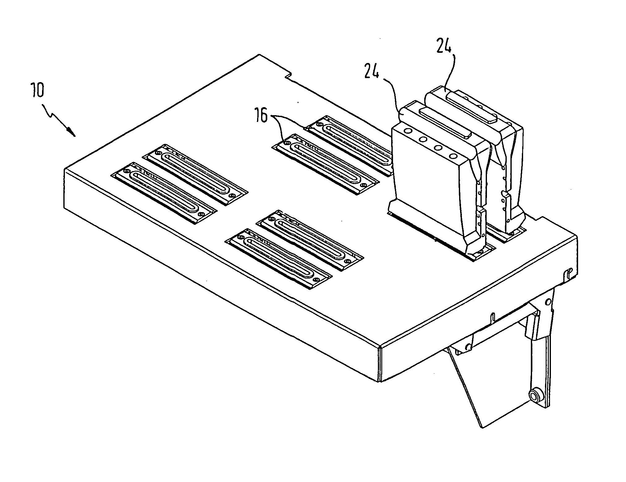
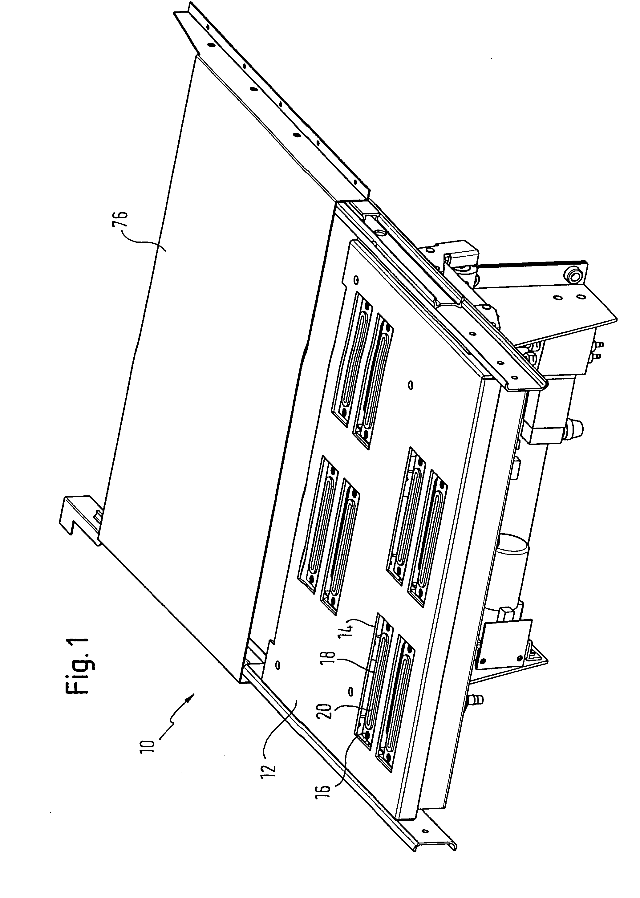
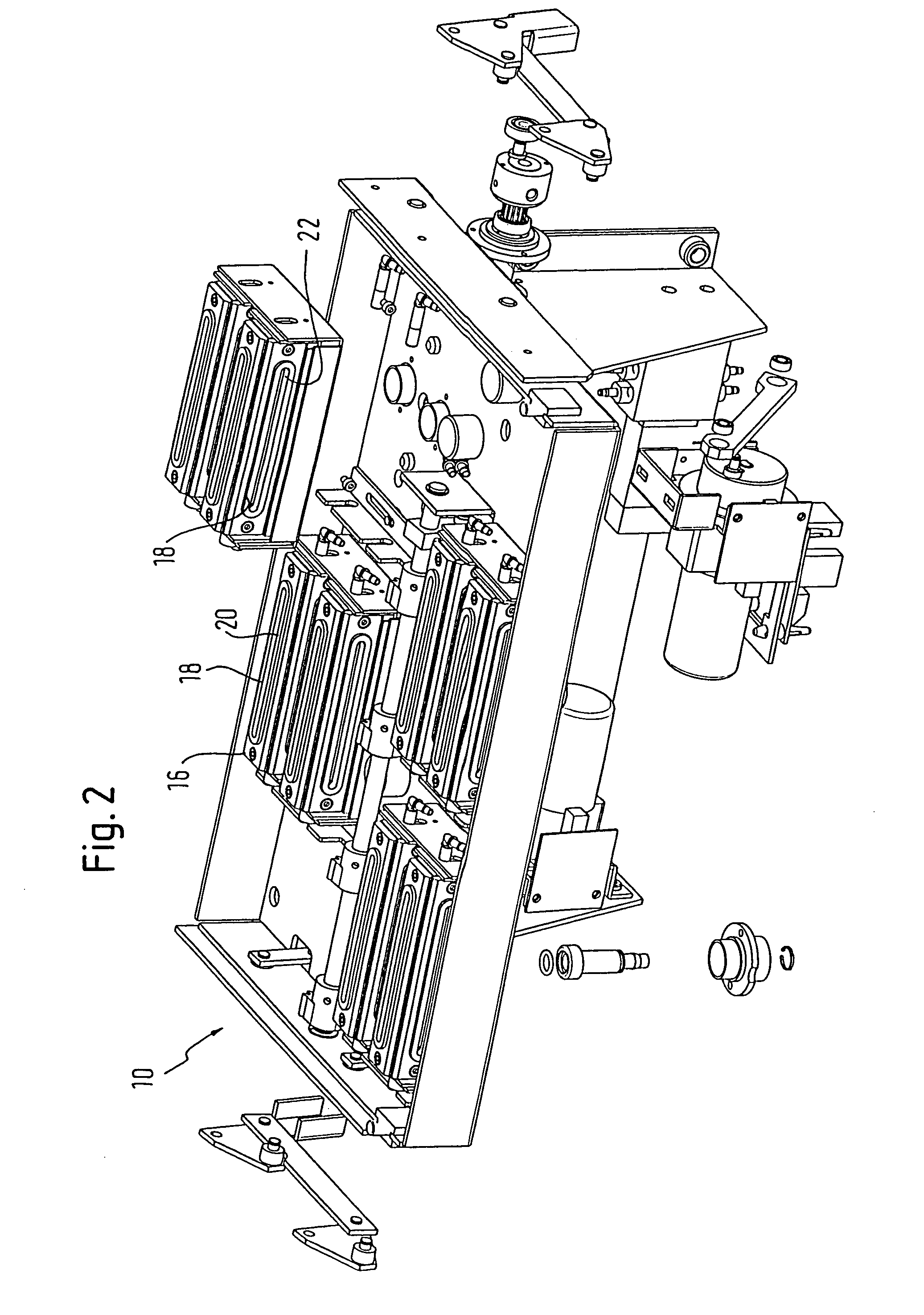
[0006] Accordingly, the cleaning unit proposed by the invention has a suction and parking cap with an orifice, which can be placed on a print head, totally preventing penetration by light. As a result, apart from being able to draw the ink off the print head to prevent incrustation of the
nozzle outlets and any uncontrolled build-up of droplets on the
nozzle outlet, this also prevents any light, in particular UV light, which would otherwise cause the ink residues to set and clog the
nozzle outlets, from reaching the print head during the suction process. The feature of being able to place the print head against the orifice of the suction and parking cap in a manner which prevents light from penetrating it is assisted by the fact that appropriate materials and covers are used to ensure that no light is able to reach any ink residues which might cause the ink to set. For example, appropriate caps may be used so that no UV light can get to the print head when it moves from its "habitual" writing position to the cleaning unit. In this respect, it should be pointed out that for the purposes of the invention, an extended guide which is necessary for moving the print
carriage can be used for a
dual purpose. If using UV ink, the movement of the
carriage needs to be extended at both sides so that the UV lamps mounted at the two sides of the print
carriage can also fully illuminate the printed region. In other words, the print head must be moved slightly to the side, outside of the printed region, so that the UV lamp mounted on the print carriage can be disposed beyond the
peripheral region of the area to which print has just been applied. Extended in this manner, a carriage guide can advantageously be used so that the print carriage, which can be moved beyond the
peripheral region on at least one side, can be arranged on a cleaning unit as proposed by the invention.
[0007] To afford protection against
exposure to UV light, both the actual cover cap which can be placed on the print head and all lines running to the orifice, which can be used to apply a vacuum in order to suck of the ink, are made from a material that is not transparent to light so that incident light which would cause the ink residues to dry on the print head can also be prevented here. It should be pointed out that in a preferred embodiment, the suction and parking cap, and preferably the entire cleaning unit proposed by the invention, is designed so that it can be raised, thereby enabling the orifice to be placed against the print head when the cap or the entire cleaning unit is raised. Alternatively, the cleaning unit could be fixed, in which case the print head would be designed so that it can be lowered onto the cleaning unit.
[0010] As mentioned above, the cleaning unit proposed by the invention, which is specifically designed for use with inks which cure under UV light, is designed to suck ink out of the ink print head. Accordingly, not only can the suction and parking cap with its orifice be placed against the print head so that it does not let light in, it also provides a
hermetic seal so that a
vacuum pressure can be applied for suction purposes. This being the case, it has been found to be of
advantage to integrate a
delay element of the first order into the
hydraulic circuit used to generate the
vacuum pressure. In other words, a
system is proposed, which has a capacity and a nozzle capable of operating a first order
delay element. Specifically, the first order
delay element consists of a capacity provided in the form of a
bottle for waste fluid. When a
vacuum pressure is applied and prevails in a pressure tank, the
system consisting of
throttle and capacity has a delaying effect. At the start,
ambient pressure prevails in the waste fluid
bottle and the pressure in this
bottle slowly drops, so that a vacuum pressure also gradually builds at the print head from which the ink is sucked. Even when the co-operating valve is shut off, the
throttle delays the return to normal pressure in the waste fluid bottle. The advantages of this are as follows. A controlled rise and fall in pressure can be obtained, which prevents parts of the ink
delivery system that are of a flexible design, for example the hoses, from contracting and then expanding during the suction process, which would cause air to be sucked into the lines, leading to undesirable bubbles in the nozzle or the lines. It should be pointed out that the feature described above does not have to be combined with the arrangement whereby the print head can be placed on the suction and parking cap to prevent light from getting in. In other words, the advantages of a delay element of the first order will still be obtained if used in conjunction with other cleaning units designed for
solvent-based inks since, it advantageously prevents air from being sucked into the ink lines and causing bubbles.
[0012] To this end, the
system may be configured in such a way that the apex of the roll is disposed on the print head outlets in its wiping position. Consequently, the entire surface of the print head outlets will be in contact with it and the ink will be soaked up by the absorbent cloth. This ensures that the print head outlets are very reliably wiped. In particular, the cloth may be moved relative to the print head outlets so that the print head outlets are wiped to a certain degree. Alternatively, the print head and the cloth may be displaced simultaneously so that the cloth is fully in contact with the surface of the print head outlets but there is no
relative displacement between the print head nozzles and the cloth, which is more gentle on the nozzles.
[0014] By preference, the suction and parking cap of the cleaning unit proposed by the invention additionally has a second orifice, into which
solvent can be introduced. This feature, which provides a particularly reliable way of "parking" the print head if using solvent-based inks, even for a longer period, because the print head outlets are rinsed with solvent, preventing the ink from setting. Although this feature is basically designed for use with solvent-based inks and has considerable advantages regardless of the feature of applying the print head against the suction and parking cap to keep out light, it is also an appropriate means of parking the print head if using inks which cure on
exposure to UV light if a second orifice is provided, which can be filled with solvent. The reason for this is that standard inks which cure on exposure to UV light also contain volatile elements and they can also thicken if left exposed, even if they are protected from UV light. The described second orifice into which solvent can be introduced to enable solvent to be applied to the print head over a longer period of time will also prevent the print head outlets from becoming clogged. To be more specific, it is preferable in this case to provide a first pump, for what could be called the parking fluid, which pumps the parking fluid, in other words a solvent, out of the parking fluid tank into the cap. A second parking fluid pump is also provided, which pumps the spent parking fluid into a waste tank.


