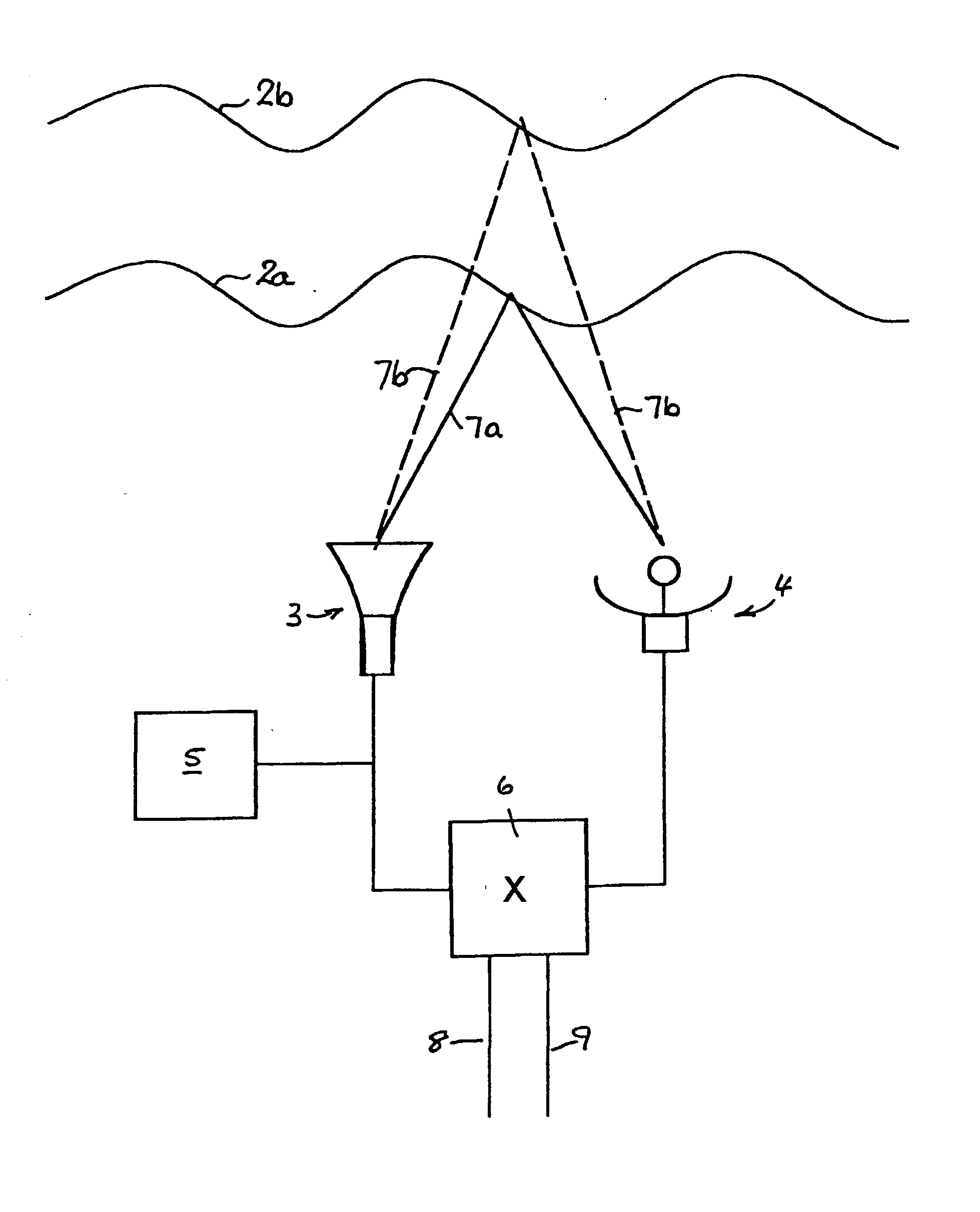
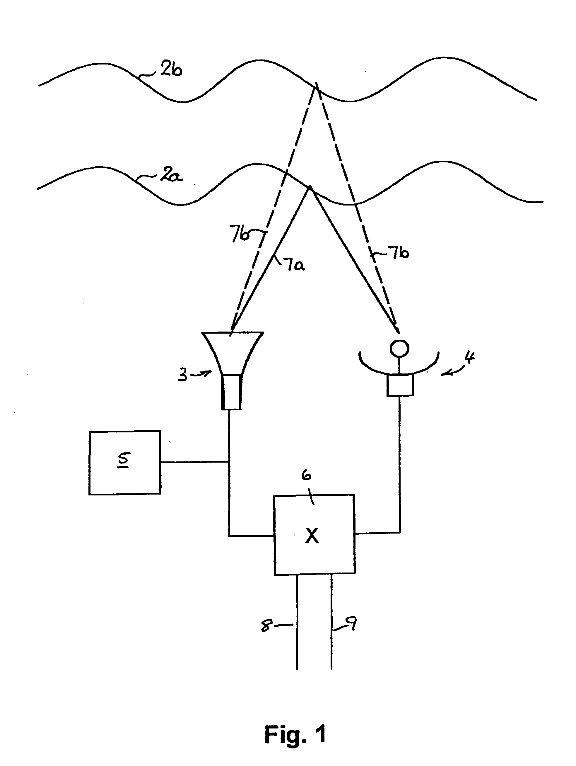
[0007] The present invention involves an acoustic sounding
system wherein the component tones in a transmitted
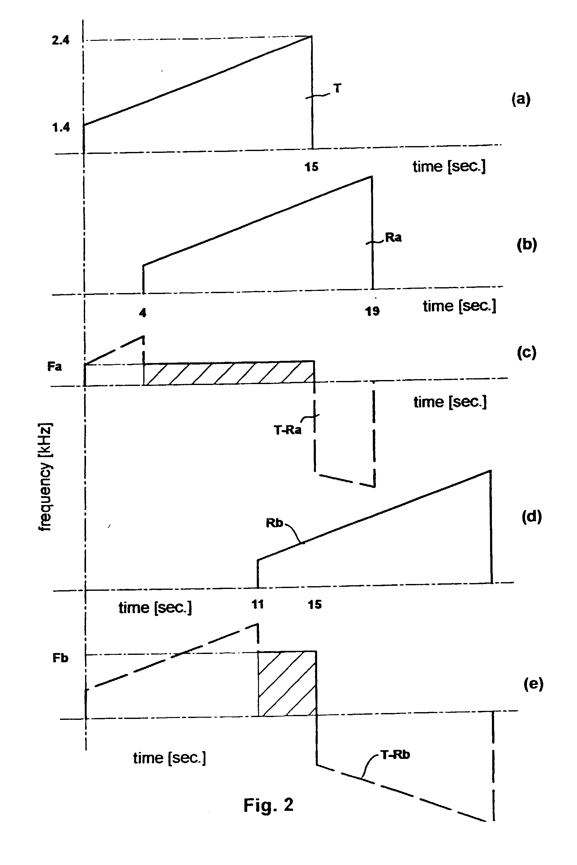
chirp are mixed, differenced, correlated or otherwise compared with the component tones in an echo chirp resulting from the reflection,
refraction and / or scattering of the transmitted chirp. In this way, chirp transit times (and therefore the location of reflecting or refracting discontinuities in range) can be indicated as a
frequency difference between the transmitted and the received chirps at any given instant. Furthermore,
phase jitter or variation in an echo tone can be detected and displayed to indicate variation in velocity of the reflecting or refracting discontinuity with respect to the
transmitter and / or
receiver. The transmitted acoustic chirp can be generated by feeding a
loudspeaker with an electrical input
signal from the
sound card of a computer (for example), while the echo chirp can be detected using a
microphone that generates an electrical
echo signal. Though the effectiveness of both loudspeaker and
microphone can be enhanced by using suitable reflector dishes, the acoustic power required in the pulse is tiny in comparison to that required for the single-tone pulse of the art.
[0013] Comparison of the input and echo signals off-line--ie, not in real time--offers the
advantage that the range of distances from which echoes are generated can be selected. Either or both the input and the echo signals can be recorded (before or after
digitization and transformation) and then jointly played back with the desired time-offset to effect their comparison. For example, if
signal processing considerations limit the chirp length to 15 s so that the maximum height at which TILs can be reliably detected in real time is, say, around 5000', the input signal can be delayed by, say, 15 s after the transmission of the acoustic chirp, so that TILs in the range of 5000 to 10000' can be detected using real-time echo signals by comparing the delayed signal with the echo signals arriving between 15 and 30 s after the start of the acoustic chirp.
[0015] As indicated above, a convenient method of generating the chirp is to feed appropriate
software (eg,
MIDI commands) to a PC
sound card so that the desired tone sequence can be generated upon command if a linear chirp is to be used, this technique allows the tone increments to be sufficiently small to create the effect of a continuous phase-shift--or smooth glissando--from beginning to end of the chirp. This input signal can be stored in a sound (wave) file in the PC and used generate repeated chirps at any desired time interval and, as already indicated, this input signal can be transmitted to a mixer for comparison with the
echo signal at any desired time. Of course, acoustic chirps should not be transmitted so frequently that echoes from multiple chirps are received at the same time. If desired, a Fourier transformed input signal may be stored in the PC so that it can be fed to the
comparator at the appropriate time for mixing with the transformed
echo signal. This technique can reduce the real-
time processing burden.
[0016] It will be appreciated that there will necessarily be direct transmission of the signal pulse from
transmitter to
receiver via the shortest
route, as well as some indirect reflections from terrestrial objects. These `direct` pulses may overlap the desired echoes in time at the receiver and degrade
echo detection and
processing. The direct pulse can be attenuated by acoustically isolating the transmitter and receiver, but this is often difficult or inconvenient. It can be subtracted from the echo chirp using known DSP techniques but, if the overlap of the direct and echo chirps is not great for the echoes of most interest,
processing in the Fourier or
frequency domain can effectively remove or discount most direct chirps. If the direct signals are not removed, the resulting amplitude-time display will show early high-amplitude returns that can be readily ignored in most cases.
[0019] The use of chirped acoustic sounders aligned with and cross-
runway such that the chirped pulses are directed at a low elevation allows windshear and CAT in the vicinity of a
runway to be identified. Preferably, mirrored transmitter and receiver sets are used in each direction so that pulses can be transmitted first in one direction and then in the other. The height of the windshear or CAT can be estimated by the time
delay between transmission and reception of the reflected or refracted pulses, while the velocity of the associated body of air in the pulse-
beam direction can be estimated by comparing the differential
time shifting of the `up` and `down` pulses. The component time-
delay measurements that allow the differential comparison can each be obtained using the techniques indicated above, yielding a highly accurate measurement of wind velocity or turbulence at any desired height within range. In general, chirp transit-time measurements conducted in this way will be more accurate than Doppler-based measurements.
[0020] As also mentioned above, the chirped acoustic pulse techniques offer substantial benefits in the characterisation of concert hall
acoustics, though the chirp duration will generally be shorter and the chirp bandwidth higher than for
atmospheric sounding. This allows highly precise measurement of the length of the principal multiple paths between a chirped pulse transmitter at a given location to a given receiver location, which then allows computation of multi-path interference for those locations over the range of audible tones. Such measurements and computations then provide most valuable inputs into the correction or optimisation of an existing concert hall.


