
Optical signal amplifier

a technology of optical signals and amplifiers, applied in the field of fiber optic communication systems, can solve the problems of increasing the likelihood of errors in transmitting information over optical fibers, requiring more than one semiconductor laser, and increasing the complexity of amplifiers, so as to minimize the fluctuation of polarization-induced gain

Inactive Publication Date: 2002-11-28
FURUKAWA ELECTRIC CO LTD
View PDF0 Cites 14 Cited by
  • Summary
  • Abstract
  • Description
  • Claims
  • Application Information

AI Technical Summary

Benefits of technology

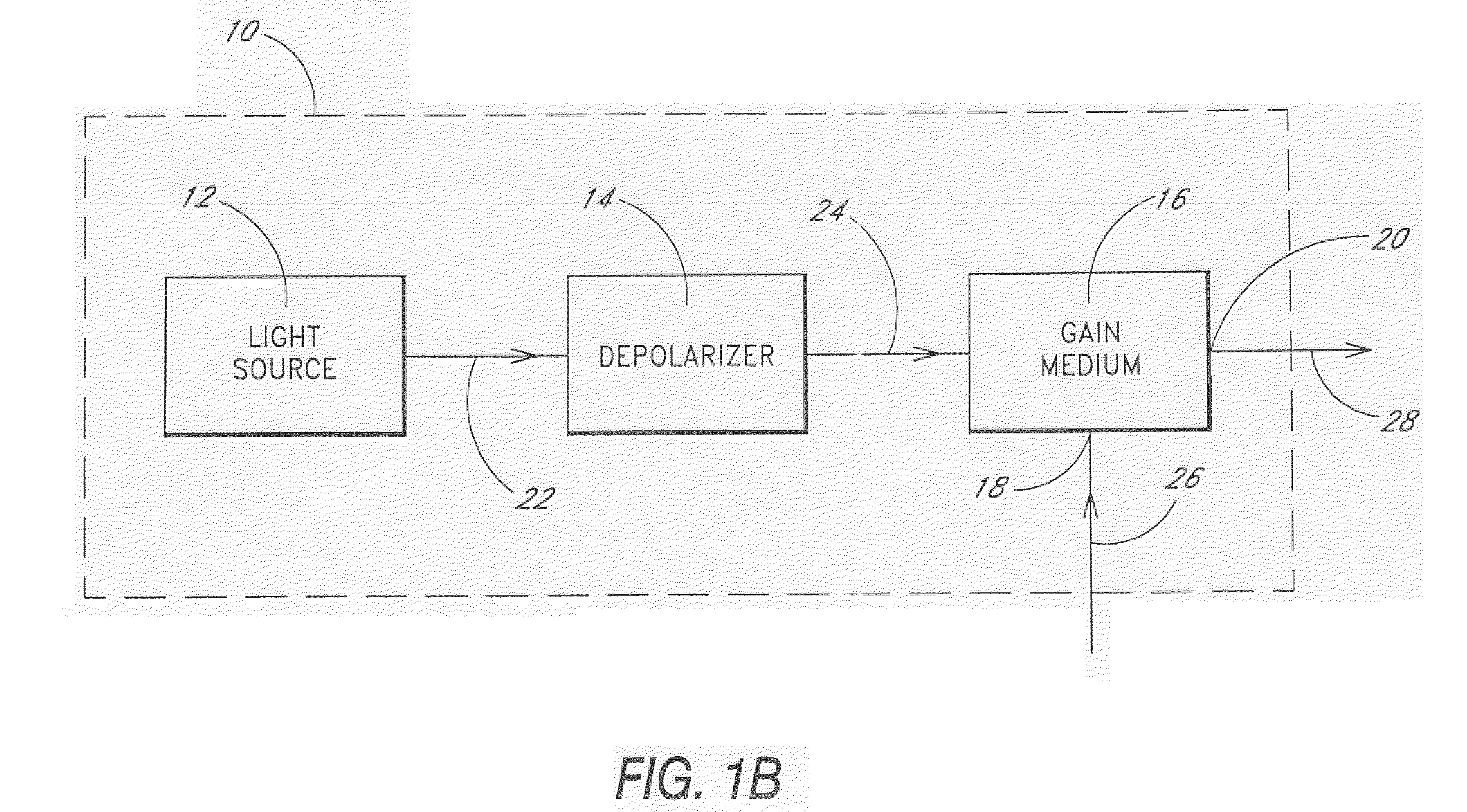
[0007] Methods of optical signal amplification include collecting light from a light source that emits at least partially polarized light divisible into light of two orthogonal linearly polarized states. This collected light is at least partially depolarized by imparting phase delay between the light of the two orthogonal linearly polarized states and is then directed into a gain medium of an optical signal amplifier. In another embodiment, a method of minimizing polarization induced gain fluctuations in an optical signal amplifier comprises at least partially depolarizing a beam of light from a first light source without combining the beam of light with a second beam of light from a second light source. This at least partially depolarized beam of light is used as a pump beam in the optical signal amplifier.

Problems solved by technology

Disadvantageously, fluctuations in the polarization of the signal or pump beam that cause the relative orientations of the electric fields to vary produce fluctuations in the gain of the amplifier.
Such fluctuations in the gain cause variations in the intensity of the optical signal, which introduces noise into the signal and thereby increases the likelihood of errors in transmitting information over optical fibers.
Although employing a plurality of semiconductor lasers can reduce the fluctuations in gain, requiring more than one semiconductor laser adds to the complexity of the amplifier.

Method used


Image

  • Optical signal amplifier
  • Optical signal amplifier
  • Optical signal amplifier

Examples


Embodiment Construction

[0024] Embodiments of the invention will now be described with reference to the accompanying Figures, wherein like numerals refer to like elements throughout. The terminology used in the description presented herein is not intended to be interpreted in any limited or restrictive manner, simply because it is being utilized in conjunction with a detailed description of certain specific embodiments of the invention. Furthermore, embodiments of the invention may include several novel features, no single one of which is solely responsible for its desirable attributes or which is essential to practicing the inventions herein described.

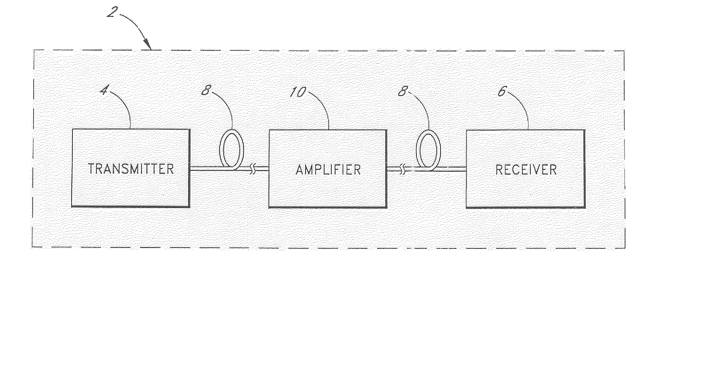
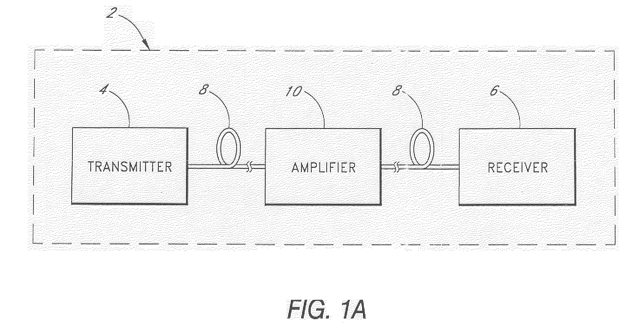
[0025] As shown in Figure 1A, a fiber optical communication system 2 comprises a transmitter 4 optically connected to a receiver 6 through an optical fiber 8. An amplifier 10 such as an optical fiber Raman amplifier may be inserted between two segments at the optical fiber 8. The transmitter 4 comprises an optical source such as a laser diode which emits an ...


PUM


Abstract

<heading lvl="0">Abstract of Disclosure< / heading> An optical signal amplifier comprises a light source, a depolarizer, and a gain medium that transfers energy from a pump beam output from the depolarizer to the optical signal. The depolarizer may comprise one or more birefringent optical fibers which support two polarization modes, a fast mode and a slow mode. The light propagates in the fast mode at a higher velocity than the light propagates in the slow mode so as to impart phase delay as the light propagates in the birefringent optical fibers, thereby at least partially depolarizing the beam.

Description

Background of Invention[0001] The present invention relates to fiber optic communications systems, and more specifically, to amplification of optical signals propagating in an optical fiber.[0002] Optical signals for conveying information in a fiber optic communication system experience attenuation as the optical signals are transmitted though an optical fiber over extended distances. The attenuated optical signal can be regenerated using amplifiers such as optical fiber Raman amplifiers, which rely on stimulated Raman scattering to transfer energy to the optical signal. The optical fiber Raman amplifier comprises a fiber that receives two input beams: a pump beam and the optical signal. Energy in the pump beam is coupled into the signal beam through stimulated Raman scattering, and the optical signal is thereby amplified upon passing through the fiber amplifier. The extent of amplification or gain depends on the relation between the polarization of the pump beam and that of the sig...

Claims


Application Information

Patent Timeline
IPC IPC(8): H01S3/094H01S3/23H01S3/30H01S5/14
CPCH01S3/094003H01S3/094073H01S5/146H01S3/2375H01S3/302H01S3/094096
Inventor MATSUSHITA , SHUNICHINAMIKI , SHUEMORI , YOSHIHIRO
Owner FURUKAWA ELECTRIC CO LTD
Learn More