
8-Mirror microlithography projection objective

a microlithography and projection objective technology, applied in the field of microlithography objectives, can solve the problems of difficult interferometric testability, limited imaging of structures of a specific size, and few correction options for imaging errors

Inactive Publication Date: 2002-10-24
CARL ZEISS SMT GMBH
View PDF2 Cites 43 Cited by
  • Summary
  • Abstract
  • Description
  • Claims
  • Application Information

AI Technical Summary

Benefits of technology

[0017] Another object of the invention is to provide a microlithography projection objective for lithography with wavelengths <193 nm, which has both a large aperture and which can be manufactured in a simple manner.
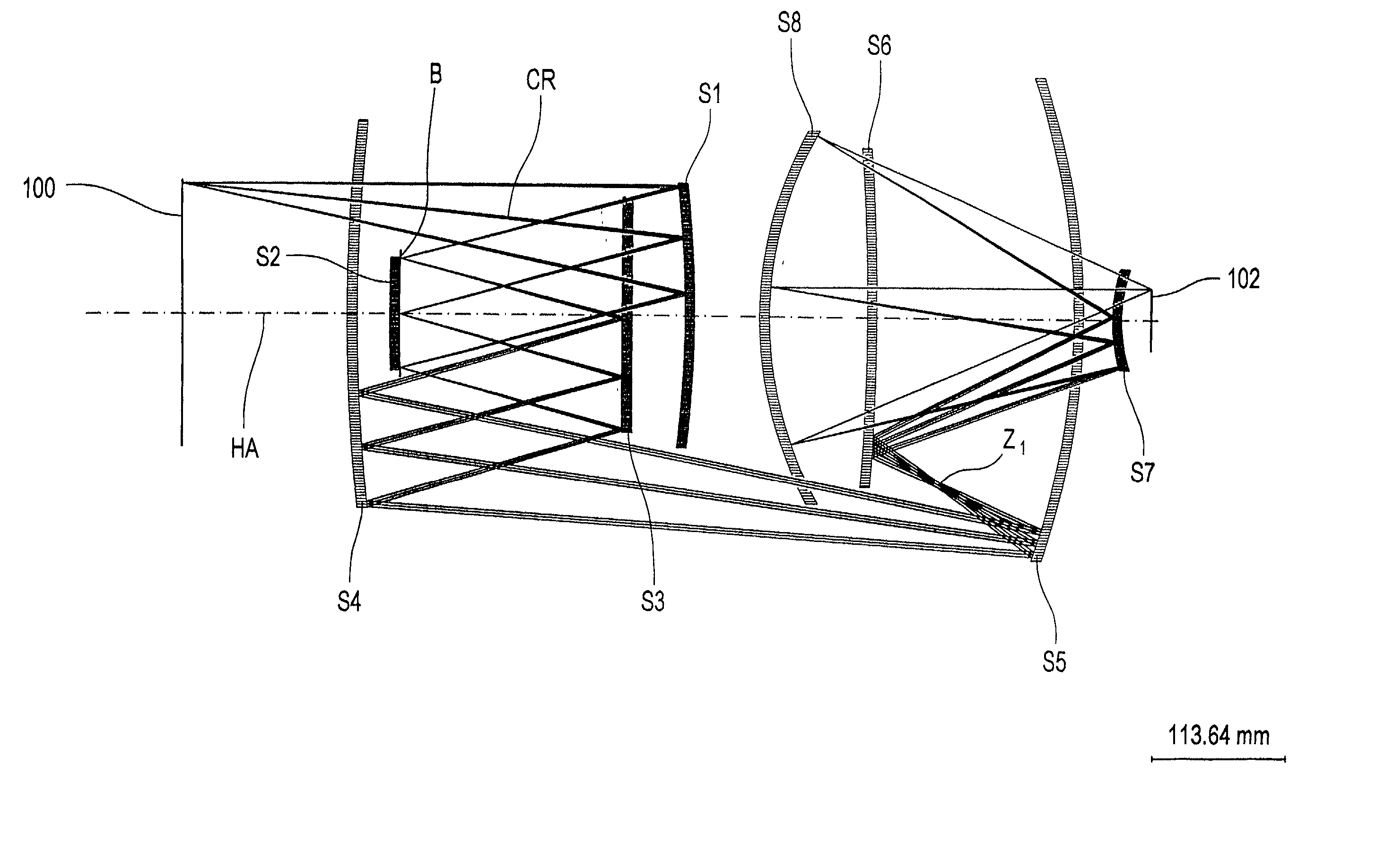
[0025] Wherein {overscore (BS)}.sub.2 denotes the distance of the diaphragm to the second mirror and {overscore (S1S2)} denotes the distance between the first and second mirror. Such an arrangement permits a minimal separation of the ray bundle in the front part of the objective. This means that the angles of incidence on the first, second and third mirrors are reduced. In addition, such an arrangement of the diaphragm yields a configuration where the off-axis segment of the third mirror lies directly below the optical axis and is nearly a mirror image of the off-axis segment of the first mirror S1. Furthermore, the angles of incidence on the fourth and fifth mirrors are reduced, since the distance of the ray bundle from the optical axis between the fourth and fifth mirrors is minimal.
[0029] In a further form of embodiment of the invention, the radius of curvature of at least one mirror is larger than the structural length of the projection objective. The distance from the object to be imaged up to its image is understood as the structural length of the system in the present application. It is particularly advantageous that the aforementioned condition for the radius of curvature applies to the second, third and fourth mirrors so that the paths of the ray bundles from the first to the second mirrors and from the third to the fourth mirrors are nearly parallel. With such a configuration, a minimal separation of the ray bundles and large drift paths is achieved. In the present application, the distance between the vertexes of two consecutive mirrors in the light path is to be understood as the drift path. The aforementioned conditions contribute to small angles of incidence on the mirrors.

Problems solved by technology

A disadvantage of a system with an exit pupil being shaded, e.g., a so-called Schwarzchild mirror system, is that structures of a specific size can be imaged only with restrictions.
Another disadvantage of both 4-mirror and 6-mirror systems is the fact that there are only a few possibilities for correction of imaging errors.
Another disadvantage of the system according to U.S. Pat. No. 5,686,728 is that all eight mirrors are formed aspheric and that the angle of the chief ray at the object has a value of 13.degree. with a numerical aperture of 0.11 on the object side.
In general the interferometric testability becomes more difficult if the distance between the off-axis segment and the optical axis becomes larger.

Method used


Image

  • 8-Mirror microlithography projection objective
  • 8-Mirror microlithography projection objective
  • 8-Mirror microlithography projection objective

Examples


Embodiment Construction

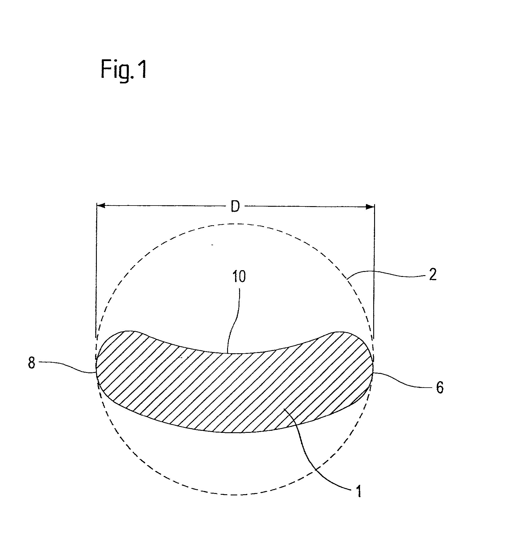
[0049] In FIG. 1 is shown what is to be understood in the present application as off-axis segments of a mirror and the diameter of such an off-axis segment.

[0050] FIG. 1 shows a kidney-shaped field as an example of a projected field 1 on a mirror of the projection objective. Such a shape is expected for the off-axis segments in an objective according to the invention, if used in a microlithography projection exposure system. The enveloping circle 2 completely encloses the kidney shape and coincides with edge 10 of the kidney shape at two points 6, 8. The enveloping circle is always the smallest circle that encloses the off-axis segment. Diameter D of the off-axis segment then results from the diameter of enveloping circle 2.

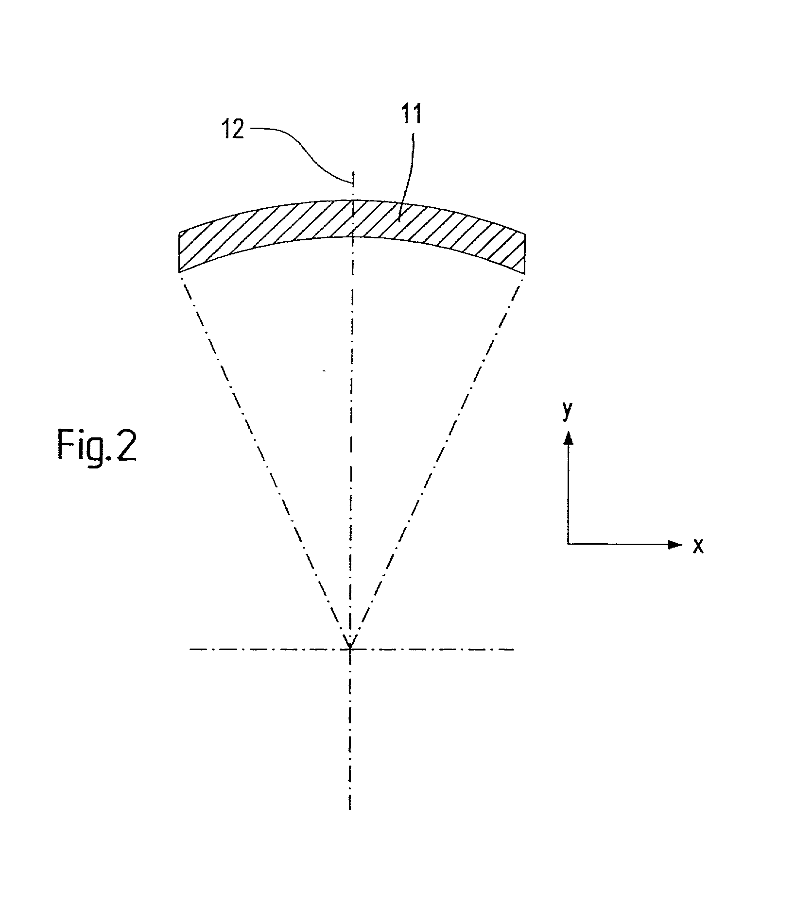
[0051] In FIG. 2, the object field 11 of a projection exposure system is shown in the object plane of the projection objective, which is imaged by means of the projection objective according to the invention in an image plane, in which a light-sensitive object, f...


PUM

PropertyMeasurementUnit
wavelengthaaaaaaaaaa
angle of incidenceaaaaaaaaaa

Abstract

A projection objective provides a light path for a light bundle from an object field in an object plane to an image field in an image plane. The projection objective comprises a first mirror (S1), a second mirror (S2), a third mirror (S3), a fourth mirror (S4), a fifth mirror (S5), a sixth mirror (S6), a seventh mirror (S7), and an eighth mirror (S8). The light path is provided via the eight mirrors, the light bundle includes light with a wavelength in the range of 10-30 nm, and the light path is free of shading.

Description

[0001] The present application is claiming priority of U.S. Provisional Patent Application Serial No. 60 / 255,216, filed on Dec. 13, 2000.[0002] 1. Field of the Invention[0003] The present invention relates to a microlithography objective for EUV lithography with a wavelength in the range of 10-30 nm for imaging an object field in an image field. The invention also provides for a projection exposure system and a chip manufacturing process.[0004] 2. Description of the Prior Art[0005] Lithography with wavelengths <193 nm, particularly EUV lithography with .lambda.=11 nm or .lambda.=13 nm are discussed as possible techniques for imaging of structures <130 nm, most preferably <100 nm. The resolution of a lithographic system is given by the following equation:RES=k.sub.1.multidot..lambda. / NA,[0006] where k.sub.1, denotes a specific parameter of the lithography process, .lambda. denotes the wavelength of the incident light and NA denotes the numerical aperture of the system on the...

Claims


Application Information

Patent Timeline
Patent Type & Authority Applications(United States)
IPC IPC(8): G02B13/24G02B17/06G03F7/20H01L21/027G02B17/00
CPCG02B17/0657G03F7/70275G03F7/70233G02B13/24
Inventor MANN, HANS-JURGENULRICH, WILHELMSEITZ, GUNTHER
Owner CARL ZEISS SMT GMBH
Learn More