
Object identification method for portable devices

Inactive Publication Date: 2002-08-01
EMBLAZE SYST
View PDF6 Cites 591 Cited by
  • Summary
  • Abstract
  • Description
  • Claims
  • Application Information

AI Technical Summary

Problems solved by technology

1. An OCR, watermark or barcode analysis software running on a PC, Workstation or a dedicated processing engine.
2. Portable devices equipped with an imaging device and computational engine for performing OCR, barcode or watermark analysis on the scanned / acquired images. The main problem with conventional devices for image based object identification is that for high quality identification powerful software is required. This software utilizes high-end processors and large quantities of memory, and hence typically runs on a non-portable device such as a personal computer. As an example for such a system is the watermark identification system called MediaBridge.TM. developed by Digimarc Inc, where the processing is done on a PC.
1. Standard barcodes, sampled by a bar-code reader, featuring a dedicated illuminator and / or detector optimized for the task of linear bar-code decoding. Pertinent examples include the barcode readers made by ConnectThings, DigitalConvergence, Gamut-interactive etc. These devices cannot decode anything by a standard barcode.
2. For performing reliable OCR using limited performance software, one may incorporate into the system a high quality, special purpose linear scanner such as the one used in the Quicktionary.TM. product by WizCom. With a special purpose scanner the OCR task becomes simpler.
3. One can limit the OCR functionality to a very limited set of alpha-numeric characters in a limited set of fonts. Hence the processing and memory requirements are reduced, making the implementation portable. The Quicktionary.TM. and Cpen.TM. devices are examples.
Another problem with conventional devices for image based object identification is that the portable devices perform lower grade recognition (such as OCR) because of power, size and price constraints, and hence give the user a limited capacity in terms of handling difficult imaging conditions, low grade print or handwriting, special fonts and different languages.
Portable devices are also harder to upgrade when new versions of software become available.
Another problem with conventional devices for image based object identification is that the portable devices are special purpose and hence have to be purchased and carried separately to provide only this function.
Furthermore, many of these devices are not connected on-line to the Internet or other on-line data bases, and hence cannot provide real-time or semi-real-time connection to data based on the scanned image, text or symbols.
While these devices may be suitable for the particular purpose to which they address, they are not as suitable for a user equipped with a portable wireless imaging device to be able to obtain information and services related to imaged objects, where the object identification is performed at least partially by a remote computational facility, and where the object identification is based on acquired images of the object.
1. In the field of algorithms and image processing operations for removing the effects of imaging under uncontrolled illumination and with low quality / limited imaging devices, there are numerous patents, see e.g. U.S. Pat. No. 5,771,312, incorporated herein by reference. The implementation of such existing algorithms and methods in the remote server for improving the image quality for human observers are also not new. The concept of developing and optimizing such algorithms as part of a remote server for improving the accuracy of the object identification is new.
2. Many algorithms exist for performing printed and hand-typed character recognition based on images, see e.g. U.S. Pat. Nos. 5,359,671, 6,011,879, 4,977,602, 5,542,006, each of these four patents is incorporated herein by reference. In the method according to the invention, one inventive aspect lies in utilizing such algorithms for performing object identification rather than e.g. performing word identification as part of inputting a printed page into a computer as text.
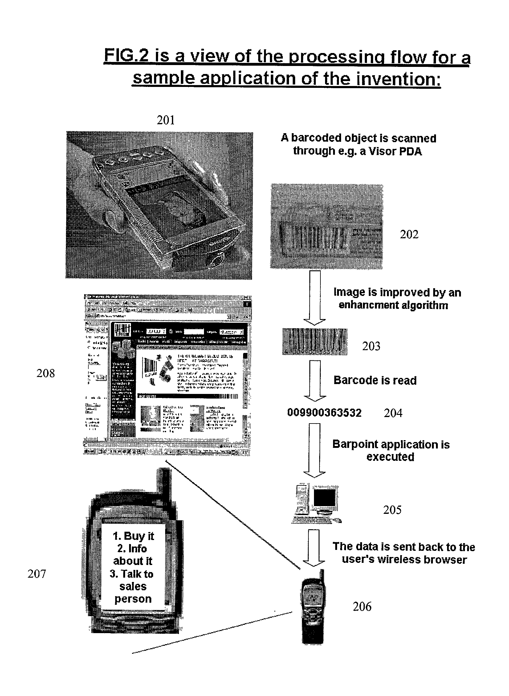
3. There is also significant prior art on using special marks or codes such as barcodes, watermarks etc for object identification, see e.g. U.S. Pat. Nos. 5,978,733, 5,933,829, each of these two U.S. patents is incorporated by reference. On the other hand, the inventive method uses standard marks such as numerals or text that appeared on the object for human reading, and emulating the human method of object identification. The limitation of using special marks is that access to the full world of objects that were not marked specifically for automated identification is not available. For example, in the case of scanning barcodes, the inventive method does not require a dedicated barcode scanner but rather it uses a standard imaging device, and it interprets the data contained in the barcode based on both the lines and the digits rather than based solely on the lines.

Method used


Image

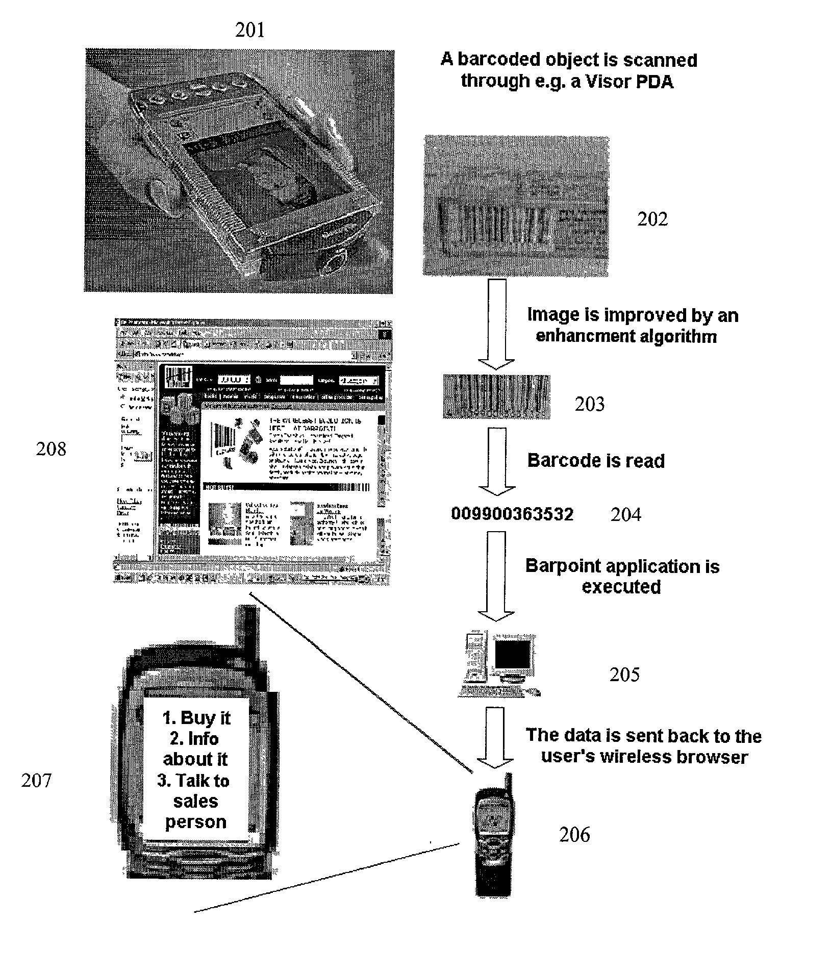
  • Object identification method for portable devices
  • Object identification method for portable devices
  • Object identification method for portable devices

Examples


Embodiment Construction

[0055] Various other objects, features and attendant advantages of the present invention will become fully appreciated as the same becomes better understood when considered in conjunction with the accompanying drawings, in which like reference characters designate the same or similar parts throughout the several views.

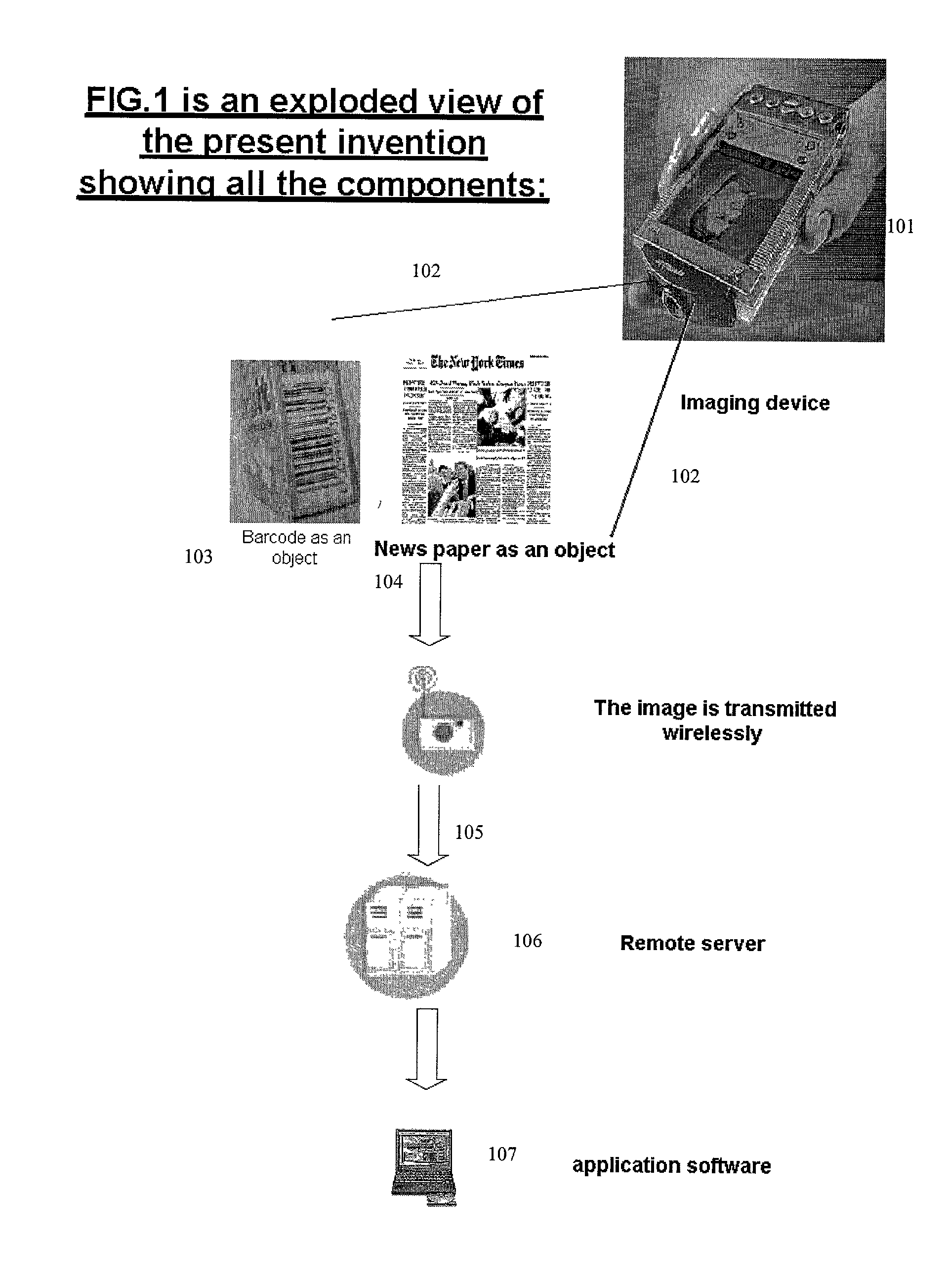
[0056] FIG. 1 is an exploded view of an embodiment of the present invention showing all the system components.

[0057] Item 101 is the imaging device, as described previously. In terms of novel additions, the imaging device may contain image compression algorithms specially optimized for the task of image compression for optimal identification rather than optimal appearance. For example, for the identification of printed text / numerals. The system can convert the image into a binary black and white image for better compression, even though it makes the image less visually appealing. Potentially, the device may run specific software--e.g. code written In J2ME, to optimize ...


PUM


Abstract

An object identification method for wireless portable devices for a user equipped with a portable wireless imaging device to be able to obtain information and services related to imaged objects, where the object identification is performed at least partially by a remote computational facility, and where the object identification is based on acquired images of the object. The method includes an imaging device, capable of taking one-dimensional or two dimensional images of objects; a device capable of sending the coded image through a wireless channel to remote facilities; algorithms and software for processing and analyzing the images and for extracting from them symbolic information such as digits, letters, text, symbols or icons; algorithms and software facilitating the identification of the imaged objects based on the information gathered from the image and the information available in databases; and algorithms and software for offering various information or services to the user of the imaging device based on the information gathered from the image and the information available in databases.

Description

[0001] The present application is based on Serial No. 60 / 245,661 filed on Nov. 6, 2000, the contents of which are hereby incorporated by reference.[0002] 1. Field of the Invention[0003] The present invention relates generally to wireless imaging technology and more specifically it relates to an object identification method for wireless portable devices for a user equipped with a portable wireless imaging device to be able to obtain information and services related to imaged objects, where the object identification is performed at least partially by a remote computational facility, and where the object identification is based on an acquired image or images of the said object. The imaging device and the wireless device can be one entity, as in a cellular phone or PDA with an integrated camera, or they can be two separate devices, as in a digital camera connected by wire or wirelessly to a cellular phone or other wireless transmission device.[0004] 2. Description of the Related Art[000...

Claims


Application Information

Patent Timeline
IPC IPC(8): G09F3/00
CPCG06K9/00G09F3/00G06F18/00
Inventor LEV, TSVI H.BAR-OR, OFER
Owner EMBLAZE SYST
Learn More